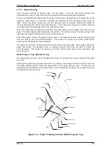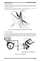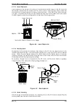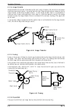
2.1.2.3 Scanner Mirror Motor Control
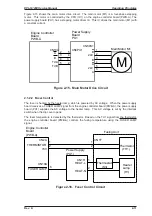
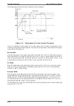
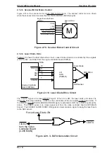
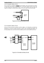
Figure 2-18 is the scanner mirror motor (M2) control circuit. The scanner mirror motor is driven
while the scanner motor receives the POLYGON MOTOR (M2:ON) signal.
2.1.2.4 Laser Diode Drive
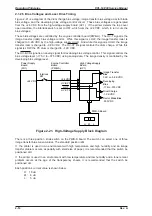
Figure 2-19 shows the laser diode drive circuit. Laser diode emission is controlled by three signals
(L DATA, DA1, and DA2) from the engine controller board (PWB-A).
The L DATA signal is the laser ON/OFF signal. When it is LOW, the laser emits, and when it is
HIGH, the laser stops emitting. L DATA is the combination of the two signals in the figure below. If
the VIDEO or the FORCED LASER DIODE ON signal is activated (LOW), the L DATA signal will be
active. The VIDEO signal is an image signal sent from the video controller board (C205 MAIN
board). The FORCED LASER DIODE ON signal is a laser emission signal to apply the laser beam
to the SOS sensor.
+24V
GND2
POLYGON MOTOR
PORYGON LOCK
PORYGON CLOCK
5
4
3
2
1
CN5A
Engine Controller Board
(PWB-A)
Scanner Motor
M2
M
Figure 2-18. Scanner Motor Control Circuit
S SCAN
CO
DA2
DA1
L DATA
Engine Controller
Board (PWB-A)
LD
SOS
(PWB-D)
Laser Diode
SOS sensor
SOS Mirror
12
11
10
7
9
CN5A
Figure 2-19. Laser Diode Drive Circuit
L DATA
Forced Laser Diode ON
VIDEO
from the Video
Controller Board
(C205 MAIN)
Figure 2-20. /L DATA Generation Circuit
EPL-N1200 Service Manual
Operating Principles
Rev. A
2-13
Summary of Contents for EPL-N1200
Page 1: ...EPSON TERMINAL PRINTER EPL N1200 SERVICE MANUAL EPSON 4006838 ...
Page 8: ...REVISION SHEET I Revision I Issue Date Revision Page Rev A December 9 1996 1st issue vii ...
Page 111: ...Chapter 4 Adjustment No adjustment is required in this product ...
Page 127: ...6 ii Rev A ...
Page 133: ...Figure A 2 Engine Section Cable Connection Appendix A EPL N1200 Service Manual A 2 Rev A ...

