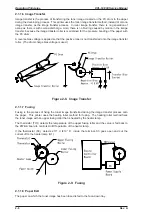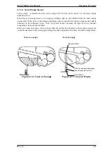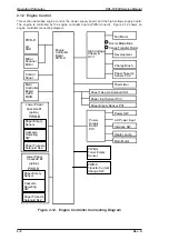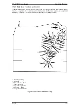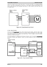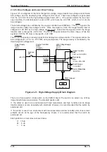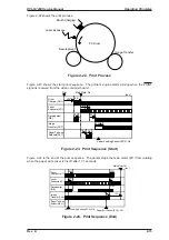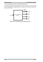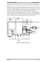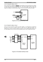
Figure 2-15 shows the main motor drive circuit. The main motor (M1) is a four-phase stepping
motor. This motor is controlled by the CPU (IC1) on the engine controller board (PWB-A). The
power supply board (PU1) has a stepping motor driver IC. This IC drives the main motor (M1) with
a constant current.
2.1.2.2 Fuser Control
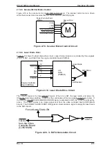
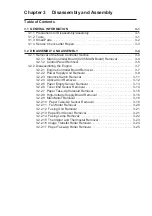
The fuser is heated by the heater lamp, which is powered by AC voltage. When the power supply
board receives a FUSER LAMP signal from the engine controller board (PWB-A), the power supply
board (PU1) supplies the AC voltage to the heater lamp. This AC voltage is cut by the interlock
switch when the top cover opens.
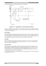
The fuser temperature is detected by the thermistor. Based on the TH1 signal from the thermistor,
the engine controller board (PWB-A) controls the fusing temperature using the FUSER LAMP
signal.
A
TdA
TdB
CN10A 2
3
4
5
5
4
3
2
CN3PU1
B
24V
B
A
24V
A
CN5PU1
1
2
3
4
5
6
Main Motor M1
Power Supply
Board
PU1
Engine Controller
Board
PWB-A
B
M
Figure 2-15. Main Motor Drive Circuit
Thermistor
(TH1)
THERMISTOR
+5V
CN2A
2
1
Fusing Unit
Thermostat
(S3)
Heater
Lamp
(H1)
HEAT-L
HEAT-N
CN1H
6
CN10A
1
2
Engine Controller
Board
(PWB-A)
Power Supply
(PU1)
FUSER LAMP
CN1T
1
2
Figure 2-16. Fuser Control Circuit
EPL-N1200 Service Manual
Operating Principles
Rev. A
2-11
Summary of Contents for EPL-N1200
Page 1: ...EPSON TERMINAL PRINTER EPL N1200 SERVICE MANUAL EPSON 4006838 ...
Page 8: ...REVISION SHEET I Revision I Issue Date Revision Page Rev A December 9 1996 1st issue vii ...
Page 111: ...Chapter 4 Adjustment No adjustment is required in this product ...
Page 127: ...6 ii Rev A ...
Page 133: ...Figure A 2 Engine Section Cable Connection Appendix A EPL N1200 Service Manual A 2 Rev A ...


