2.1 ENGINE OPERATION
This section describes the functions and operating principles of the EPL-N1200 engine.
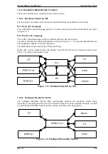
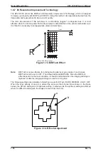
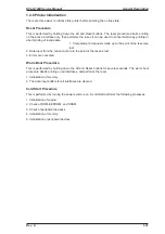
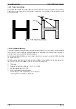
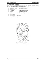
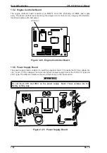
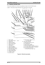
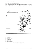
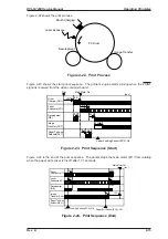
Figure 2-1 shows the locations and names of the main engine components.
1.
Paper Guide
16. Paper Take-up Sensor Lever
2.
Paper Empty Sensor
Lever
17. Transfer Roller
3.
Optical Unit
18. Paper Take-up Roller
4.
Imaging Cartridge
19. Paper Empty Sensor Lever
5.
Paper Take-up Roller
20. Transfer Roller
6.
Heater Lamp (H1)
21. Paper Take-up Roller
7.
Thermostat
22. Paper Empty Sensor Lever
8.
Paper Exit Roller
23. 2nd Lower Paper Cassette Unit (Option)
9.
Upper Fusing Roller
24. 1st Lower Paper Cassette Unit (Option)
10. Paper Exit Sensor Lever
25. Power Supply Unit (PU1)
11. Paper Exit Sensor (PC3)
26. Multi- Purpose Paper Tray
12. Lower Fusing Roller
13. Image Transfer Roller
14. Cooling Fan (M3))
15. Main Motor (M1)
Figure 2-1. Main Components
1
2
23
24
25
26
22
21
20
19
18
4
3
5
6
7
8
9
10
11
12
13
14
15
16
17
EPL-N1200 Service Manual
Operating Principles
Rev. A
2-1
Summary of Contents for EPL-N1200
Page 1: ...EPSON TERMINAL PRINTER EPL N1200 SERVICE MANUAL EPSON 4006838 ...
Page 8: ...REVISION SHEET I Revision I Issue Date Revision Page Rev A December 9 1996 1st issue vii ...
Page 111: ...Chapter 4 Adjustment No adjustment is required in this product ...
Page 127: ...6 ii Rev A ...
Page 133: ...Figure A 2 Engine Section Cable Connection Appendix A EPL N1200 Service Manual A 2 Rev A ...


