


Maintenance 4. Replacing the Cable Unit
E2C Rev.6
87
4.2.1 S, C Type Manipulators
Removal
(1) Turn OFF the Controller.
(2) Disconnect all the connectors and tubes from the base connector box (outside).
(3) Remove the base connector box.
For details on the removal method, refer to
Maintenance: 3.4 Base Connector Box
.
Remember the cable layout so that the cables can be reconnected correctly after
replacement.
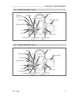
(4) Remove the connector cover and cut off
the wire tie binding cables.
Detach the ferrite core.
(5) Disconnect X110 connector by holding the
claw next to the connector number on the
motor side.
Wire tie
Ferrite core
Connector
cover
Connector box
(6) Remove the receptacle from the base
connector box.
(7) Disconnect the pneumatic tubes and
ground terminal from the base connector
box (inside).
To disconnect the pneumatic tube, push the
ring on each pneumatic tube fitting and
pull out its tube.
To disconnect the ground terminal,
unscrew the bolt from the ground terminal.
(8) Disconnect X20, X30, X40, and X50
connectors from the signal relay board.
Receptacle
4-M3
×
8
Ground terminal
Pneumatic tube
fittings
8-M4
×
8
Be sure to connect motors to the signal relay board with a new cable unit within 2
hours after the connectors are disconnected. Otherwise, the motor will lose position
data and the calibration must be executed again.
)
NOTE
)
NOTE
Summary of Contents for E2C Series
Page 1: ...SCARA ROBOT E2C series MANIPULATOR MANUAL Rev 6 EM069R1409F ...
Page 2: ...MANIPULATOR MANUAL E2C series Rev 6 ...
Page 8: ...vi E2C Rev 6 ...
Page 14: ......
Page 82: ......
Page 92: ...Maintenance 2 General Maintenance 80 E2C Rev 6 ...
Page 118: ...Maintenance 4 Replacing the Cable Unit 106 E2C Rev 6 ...
Page 194: ...Maintenance 11 Replacing the Signal Relay Board 182 E2C Rev 6 ...


