


Setup & Operation 5. Motion Range
E2C Rev.6
55
5.
1
.
1
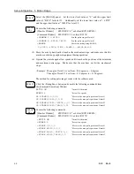
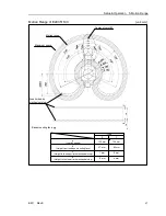
Max. Pulse Range of Joint #
1
0 (zero) pulse position of Joint #1 is the position where Arm #1 faces toward the positive
(+) direction on the X-coordinate axis.
When the 0 pulse is a starting point, the counterclockwise pulse value is defined as the
positive (+) and the clockwise pulse value is defined as the negative (
-
).
+Y
+X
0 pulse
+
1
63840 pulse
0 pulse
E2C25
1
*
(Table Top)
-
90 deg.
+90 deg.
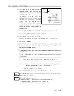
+Y
+X
0 pulse
+
1
82045 pulse
-
1
8205 pulse
E2C35
1
*
(Table Top)
+Y
+X
0 pulse
+
1
82045 pulse
-
1
8205 pulse
E2C35
1
*M
(Multiple Mountings)
-
11
0 deg.
+
11
0 deg.
-
11
0 deg.
+
11
0 deg.
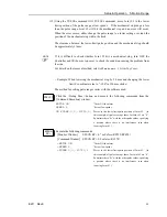
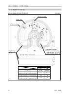
5.
1
.2 Max. Pulse Range of Joint #2
0 (zero) pulse position of Joint #2 is the position where Arm #2 is parallel to Arm #1.
With the 0 pulse as a starting point, the counterclockwise pulse value is defined as the
positive (+) and the clockwise pulse value is defined as the negative (
-
).
-
76800 pulse
+76800 pulse
0 pulse
E2C25
1
*
(Table Top)
+
1
35 deg.
-
1
35 deg.
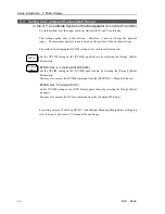
-
82489 pulse
+82489 pulse
0 pulse
0 pulse
-
82489 pulse
+82489 pulse
E2C35
1
*
(Table Top)
E2C35
1
*M
(Multiple Mountings)
+
1
45 deg.
-
1
45 deg.
+
1
45 deg.
-
1
45 deg.
Summary of Contents for E2C Series
Page 1: ...SCARA ROBOT E2C series MANIPULATOR MANUAL Rev 6 EM069R1409F ...
Page 2: ...MANIPULATOR MANUAL E2C series Rev 6 ...
Page 8: ...vi E2C Rev 6 ...
Page 14: ......
Page 82: ......
Page 92: ...Maintenance 2 General Maintenance 80 E2C Rev 6 ...
Page 118: ...Maintenance 4 Replacing the Cable Unit 106 E2C Rev 6 ...
Page 194: ...Maintenance 11 Replacing the Signal Relay Board 182 E2C Rev 6 ...