


Maintenance 5. Replacing the Motors (Joint #4)
122
E2C Rev.6
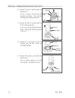
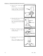
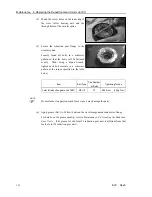
(4) Place the U1 belt around the large U2
pulley and the U1 pulley.
Make sure that the gear teeth of the belt
mesh with the pulleys completely.
4-M4×
1
2
+Washer,
Spring
washer
Motor plate
U
1
belt
U
1
pulley
(5) Loosely secure the Joint #4 motor unit to Arm #2.
Loosely secure the Joint #4 motor unit to Arm #2 so that the motor unit can be moved
by hand, and it will not tilt when pulled. If the unit is secured too loose or too tight,
the belt will not have the proper tension.
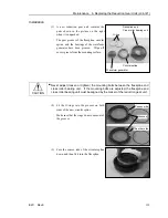
(6) Apply the proper tension to the U1 belt,
and secure the Joint #4 motor unit.
To do so, pass a suitable cord or string
around the Joint #4 motor unit near its
mounting plate. Then, pull the cord using
a force gauge or similar tool to apply the
specified tension shown in the figure on
the right.
Tension of U
1
belt: 39.2 N (4 kgf)
Adjustable range:
29.4–49.0 N (3–5 kgf)
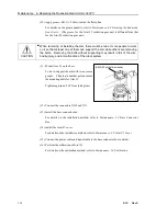
4-M4×
1
2+Washer, Spring washer
(7) Mount the duct plate on Arm #2.
(8) Connect the connectors X141 and X41.
(9) Re-bundle the cables in their original positions with a wire tie.
Do not allow unnecessary strain on the cables.
(10) Install the arm top cover.
For details on the installation method, refer to
Maintenance: 3.1 Arm Top Cover
.
(11) Perform the calibration of Joint #4.
For details on the calibration method, refer to
Maintenance: 14. Calibration
.
)
NOTE
Summary of Contents for E2C Series
Page 1: ...SCARA ROBOT E2C series MANIPULATOR MANUAL Rev 6 EM069R1409F ...
Page 2: ...MANIPULATOR MANUAL E2C series Rev 6 ...
Page 8: ...vi E2C Rev 6 ...
Page 14: ......
Page 82: ......
Page 92: ...Maintenance 2 General Maintenance 80 E2C Rev 6 ...
Page 118: ...Maintenance 4 Replacing the Cable Unit 106 E2C Rev 6 ...
Page 194: ...Maintenance 11 Replacing the Signal Relay Board 182 E2C Rev 6 ...