


Maintenance 6. Replacing the Reduction Gear Units (Joint #2)
144
E2C Rev.6
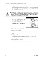
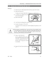
(11) Mount the Joint #2 motor unit on Arm #1.
Make sure that the motor cables face
toward the direction as shown in the figure
on the right.
Joint #2
motor unit
3-M4
×
10
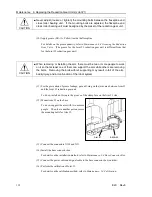
CAUTION
■
When removing or installing the arm, there must be two or more people to work
on it so that at least one of them can support the arm while others are removing
the bolts. Removing the bolts without supporting may result in fall of the arm,
bodily injury, and/or malfunction of the robot system.
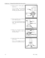
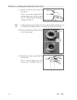
(12) Mount Arm #2 on Arm #1.
To do so, support the arm with two or more
people. Then, have another person secure
the mounting bolts for Arm #2.
4-M5
×
15
Arm #2
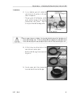
(13) Mount the duct plate on Arm #2.
Duct plate
3-M5
×
15
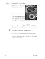
(14) Connect the connectors X121 and X21.
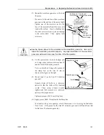
(15) Re-bundle the cables in their original positions with a wire tie.
Do not allow unnecessary strain on the cables.
(16) Install the arm top cover.
For details on the installation method, refer to
Maintenance: 3.1 Arm Top Cover
.
(17) Connect the power cable and signal cable to the base connector box (outside).
(18) Perform the calibration of Joint #2.
For details on the calibration method, refer to
Maintenance: 14. Calibration
.
Summary of Contents for E2C Series
Page 1: ...SCARA ROBOT E2C series MANIPULATOR MANUAL Rev 6 EM069R1409F ...
Page 2: ...MANIPULATOR MANUAL E2C series Rev 6 ...
Page 8: ...vi E2C Rev 6 ...
Page 14: ......
Page 82: ......
Page 92: ...Maintenance 2 General Maintenance 80 E2C Rev 6 ...
Page 118: ...Maintenance 4 Replacing the Cable Unit 106 E2C Rev 6 ...
Page 194: ...Maintenance 11 Replacing the Signal Relay Board 182 E2C Rev 6 ...