EPSON Stylus PHOTO 2100/2200
Revision B
OPERATING PRINCIPLES
Printer Mechanism
43
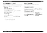
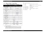
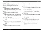
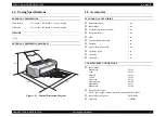
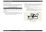
2.2.1.3 Sequence Used for PW Detection
The PW detector on the Carriage unit bottom performs the following sequence.
!
Off-paper printing prevention control
Before start of printing (immediately after the end of paper locating) or during
printing, whether paper is present or not is detected to prevent off-paper printing
onto the Paper guide. (Applied to only the left or right end of the paper)
If the sent data has the paper size that is larger than the fed paper size, trimming is
executed according to the paper size detected by the PW sensor, and frame
printing is performed (frame width 2mm). Reversely, if the received data has the
paper size that is smaller than the fed paper size, frame printing is also performed.
This feature is designed to prevent off-paper printing onto the Paper guide by
frameless printing performed in a wrong using method. However, in the fast mode
for plain paper or postcards, paper width detection is not executed to improve the
throughput. When the above using method is performed, the specifications of
trimming and frame printing are not applied.
!
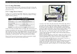
CD-R center detection control (Only for Stylus PHOTO 2100)
When printing is not being performed, the PW detector is used to detect the center
of CD-R.
Refer to 2.2.3.6 "CD-R Printing Mechanism (Only for Stylus PHOTO 2100)" for
details.
!
Board paper/roll paper leading edge detection control
Control exercised to detect the user-preset board paper leading edge, or control
carried out to detect the roll paper edge. Therefore, the PW sensor does not detect
a paper leading edge at the time of ASF cut sheet feeding.
!
Off-range restriction control
At the time of frameless printing, a paper leading edge is detected using the PW
detector to restrict the frameless off-range amount.
"
Auto sheet feeder complete frameless mode
In the complete frameless mode, control is performed to print the print data
3mm larger at top, 5mm larger at bottom, and 2.5mm lager at left and right
than the detected paper size.
(3mm larger at top, 5mm larger at bottom, and 3.5mm lager at left and right
for A3 or A3+ size)
"
Roll paper mode
In the left and right frameless mode, control is performed to print the print
data 2.5mm lager at left and right than the detected paper size.
(3mm larger at top, 5mm larger at bottom, and 2.5mm lager at left and right
when the fixed-format mode is selected)
!
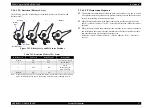
PW sensor dark voltage (VH) measurement
PW sensor dark voltage (VH) measurement is performed at the following timings
and locations and used to calculate the threshold value of whether paper is present
or not.
"
Cut sheets, Roll paper
The dark voltage is measured and updated at every power-on, and the
threshold value (VS) is calculated and saved in the EPROM 76<H> area as a
PW detection level. The dark voltage is measured at 3poinst on the left flat
portion of the the Paper Guide Front. If the PW level measured in the Papaer
width measuerment sequence is less than the PW detection level stored in the
EEPROM, it means the sensor is detecting the paper.
"
CD-R tray (Only for Stylus PHOTO 2100)
When a CD-R is used, the dark voltage is measured on the CD-R tray, and the
threshold valve (VS) is then calculated and saved in the EPROM 76<H> area
as a PW detection level.
If the PW sensor level measured in the CD-R HP detection sequence & CD-R
center position detection sequence is less than the PW detection level stored in
the EEPROM, it means the sensor is detecting the HP of the CD-R tray and
the CD-R on the tray.
Every paper or CD-R tray is loaded, the voltage measured on the Paper or
CD-R tray is stored in the EEPROM BB<H> area as a white level.
Summary of Contents for 2200 - Stylus Photo Color Inkjet Printer
Page 1: ...EPSONStylusPHOTO2100 2200 Color Inkjet Printer SEIJ01 016 SERVICE MANUAL ...
Page 8: ...C H A P T E R 1 PRODUCTIONDESCRIPTION ...
Page 39: ...C H A P T E R 2 OPERATINGPRINCIPLES ...
Page 69: ...C H A P T E R 3 TROUBLESHOOTING ...
Page 115: ...C H A P T E R 4 DISASSEMBLYANDASSEMBLY ...
Page 187: ...C H A P T E R 5 ADJUSTMENT ...
Page 214: ...C H A P T E R 6 MAINTENANCE ...
Page 226: ...C H A P T E R 7 APPENDIX ...
Page 254: ......
Page 255: ......
Page 256: ......
Page 257: ......
Page 258: ......

