EPSON Stylus PHOTO 2100/2200
Revision B
DISASSEMBLY AND ASSEMBLY
Disassembly
151
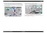
6.
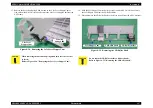
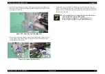
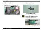
Lift the right end of the Carriage Guide Shaft B as seen from the printer front,
remove the Sub Shaft Fixing Plate (Right) from the hook of the Right Frame, and
turn the Sub Shaft Fixing Plate (Right) to remove it from the Carriage Guide Shaft
B.
Figure 4-69. Removing the Sub Shaft Fixing Plate (Right)
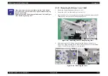
7.
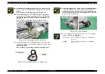
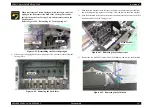
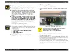
Slide the Carriage Guide Shaft B to the right as seen from the printer front, then
remove the left end from the Frame, and remove the Carriage Guide Shaft B to the
diagonal top left of the Printer Mechanism.
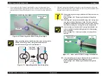
When reinstalling the Sub Shaft Fixing Plate to the Carriage Guide
Shaft B, insert the leg of the Carriage Guide Shaft B in the
direction shown in Figure 4-70 and then turn it.
Figure 4-70. Reinstalling the Sub Shaft Fixing Plate
Hook
Carriage Guide
Shaft B
Sub Shaft Fixing Plate (Right)
Carriage
Guide Shaft
B
Sub Shaft
Fixing Plate
C A U T I O N
"
When removing the Carriage Guide Shaft B, fully take care not
to scratch it.
Refer to Figure 4-69, "Removing the Sub Shaft Fixing Plate
(Right)".
"
Removing the Carriage Guide Shaft B brings the Carriage Unit
into contact with the Front Paper Guide. Therefore, when the
Printhead is installed on the Carriage Unit, remove the Carriage
Shaft B after moving the Carriage Unit to the home position.
"
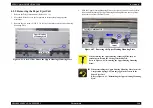
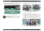
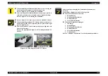
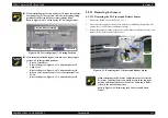
Make sure that the left end of the Carriage Guide Shaft B is in
order of the Bush, Sub Shaft Fixing Plate (Left), Plain Spring
and Leaf Spring.
Refer to Figure 4-71, "Order on Left End of Carriage Guide
Shaft B".
Figure 4-71. Order on Left End of Carriage Guide Shaft B
"
After reinstalling the Carriage Guide Shaft B, always make sure
that the Sub Shaft Fixing Plate is mounted correctly.
Refer to Figure 4-69, "Removing the Sub Shaft Fixing Plate
(Right)".
Plain Spring
Sub Shaft Fixing
Plate (Left)
Bush
Leaf
Spring
×
2
Summary of Contents for 2200 - Stylus Photo Color Inkjet Printer
Page 1: ...EPSONStylusPHOTO2100 2200 Color Inkjet Printer SEIJ01 016 SERVICE MANUAL ...
Page 8: ...C H A P T E R 1 PRODUCTIONDESCRIPTION ...
Page 39: ...C H A P T E R 2 OPERATINGPRINCIPLES ...
Page 69: ...C H A P T E R 3 TROUBLESHOOTING ...
Page 115: ...C H A P T E R 4 DISASSEMBLYANDASSEMBLY ...
Page 187: ...C H A P T E R 5 ADJUSTMENT ...
Page 214: ...C H A P T E R 6 MAINTENANCE ...
Page 226: ...C H A P T E R 7 APPENDIX ...
Page 254: ......
Page 255: ......
Page 256: ......
Page 257: ......
Page 258: ......

