EPSON Stylus PHOTO 2100/2200
Revision B
DISASSEMBLY AND ASSEMBLY
Disassembly
174
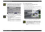
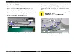
11. Remove the two screws 14) C.B.P 3
×
8 (6
±
1kgf.cm) that secure the ASF/Pump
Motor.
12. Disconnect the Cable of the ASF/Pump Motor from the hook of the DE unit.
13. Slide the ASF/Pump Motor to the bottom right as seen from the DE Unit front to
remove it from the DE Unit. (The DE Unit is also removed.)
Figure 4-121. Screws That Secure the ASF/Pump Motor
C.B.P 3
×
8
Hook
DE Unit front
Circuit Board
"
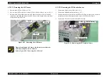
When reinstalling the ASF/Pump Motor, face the Circuit Board
of the Motor upward.
Refer to Figure 4-121, "Screws That Secure the ASF/Pump
Motor".
"
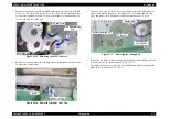
To reinstall the ASF/Pump Motor to the DE Unit, lower the
Planetary Lever Unit, insert the Pinion Gear of the ASF/Pump
Motor into the ASF/Pump Motor positioning hole, and slide it to
the top left side.
Refer to Figure 4-122, "How to Install the ASF/Pump Motor".
Figure 4-122. How to Install the ASF/Pump Motor
A D J U S T M E N T
R E Q U I R E D
"
After changing the following parts for new ones, always apply
grease G-26 or oil O-12 in the specified positions.
•
Combination Gear 12, 22.4, Combination Gear 14, 28, ASF
Motor Mounting Plate, Felt D3.6:
Refer to Chapter 6, Figure 6-6, "Lubrication Point 4, 5, 6, 7,
8".
•
Spur Gear 26.4, Compound Gear Lever Assembly:
Refer to Chapter 6, Figure 6-13, "Lubrication Point 15".
Planetary
Lever Unit
Positioning hole
Summary of Contents for 2200 - Stylus Photo Color Inkjet Printer
Page 1: ...EPSONStylusPHOTO2100 2200 Color Inkjet Printer SEIJ01 016 SERVICE MANUAL ...
Page 8: ...C H A P T E R 1 PRODUCTIONDESCRIPTION ...
Page 39: ...C H A P T E R 2 OPERATINGPRINCIPLES ...
Page 69: ...C H A P T E R 3 TROUBLESHOOTING ...
Page 115: ...C H A P T E R 4 DISASSEMBLYANDASSEMBLY ...
Page 187: ...C H A P T E R 5 ADJUSTMENT ...
Page 214: ...C H A P T E R 6 MAINTENANCE ...
Page 226: ...C H A P T E R 7 APPENDIX ...
Page 254: ......
Page 255: ......
Page 256: ......
Page 257: ......
Page 258: ......


