EPSON Stylus PHOTO 2100/2200
Revision B
OPERATING PRINCIPLES
Printer Mechanism
42
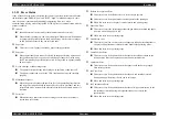
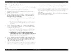
2.2.1.2 Carriage Home Position Detection
To detect the Carriage home position, the drive current of the CR motor and the speed/
position signal of the CR linear encoder are used as in the conventional Stylus PHOTO
2000P.
The basic home position detection sequence is as described below.
1.
The CR linear encoder pulse counter in the CPU is reset by the initialization
operation performed at power-on.
2.
When the CR motor rotates counterclockwise, the Carriage moves from left to
right. When the following conditions are satisfied, the CPU assumes that the
Carriage made contact with the right frame.
2.1 When the ASIC detected 750/1500 counts or more in the PWM output
under CR motor load positioning control, the temporary home position A
is set as contact with the frame.
2.2 P1 (number of output pulses from when power is switched on until the
Carriage makes contact with the right frame) is 40 steps or less between
reset 0 and A.
3.
When the CR motor rotates clockwise, the Carriage moves from right to left.
When the following conditions are satisfied, the CPU assumes that the Carriage
made contact with the CR lock lever.
3.1 When the ASIC detected 480/1500 counts or more in the PWM output
under CR motor load positioning control, the printer judges that the
Carriage made contact with the CR lock lever.
3.2 A difference between P2 (number of output pulses from when the
Carriage made contact with the right frame until it makes contact with the
Carriage lock lever) and P1 is yy or less, and the number of outputs
between A and CR lock lever is 40 steps or less.
4.
When the CR motor rotates counterclockwise to move the Carriage from left to
right and the CPU detects 750/1500 counts or more in the PWM output under CR
motor load positioning control, the printer judges it as contact with the frame.
At this time, the carriage position B is stored.
5.
If a difference between P3 (number of output pulses from when the Carriage made
contact with the Carriage lock lever until it makes contact with the right frame)
and P1 has become Z or less, the printer judges that the Carriage is in the home
position. If a position difference between the temporary home position A and the
second frame contact position B is 4 steps or less, the printer judges it as a home
position.
Based on the output pulses (signals) from the CR linear encoder, the IC30 (ASIC) sets
the drive current value adequate for the carriage motion (carriage moving direction and
carriage position) of each operation and outputs it to the motor driver as a special
control signal.
Based on the signal output from the IC30 (ASIC), the IC24 (CR motor driver) outputs
the CR motor drive current to the CR motor.
Summary of Contents for 2200 - Stylus Photo Color Inkjet Printer
Page 1: ...EPSONStylusPHOTO2100 2200 Color Inkjet Printer SEIJ01 016 SERVICE MANUAL ...
Page 8: ...C H A P T E R 1 PRODUCTIONDESCRIPTION ...
Page 39: ...C H A P T E R 2 OPERATINGPRINCIPLES ...
Page 69: ...C H A P T E R 3 TROUBLESHOOTING ...
Page 115: ...C H A P T E R 4 DISASSEMBLYANDASSEMBLY ...
Page 187: ...C H A P T E R 5 ADJUSTMENT ...
Page 214: ...C H A P T E R 6 MAINTENANCE ...
Page 226: ...C H A P T E R 7 APPENDIX ...
Page 254: ......
Page 255: ......
Page 256: ......
Page 257: ......
Page 258: ......

