background image

APPENDIX C: SYSTEM CALIBRATION

Camera Calibration

Note: 

Camera calibration on the Fusion 

Pro is only necessary if recommended 

by Epilog’s Technical Support. 

Note:

 Before beginning, reboot your 

machine if you have recently run any 

jobs.

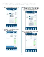
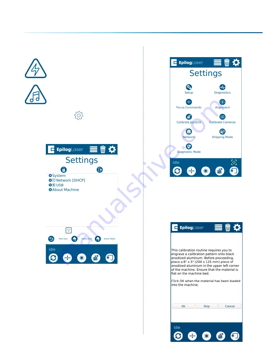
1.  Click the 

Settings


button to enter the 

Settings menu. 

2.  Long Press the 

“Settings”

 text for 5 seconds 

to enter the Advanced Settings Menu.

3.  Click on 

“Calibrate Cameras” 

to enter the 

Camera Calibration menu.

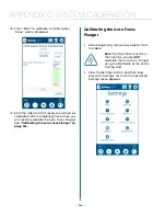
4.  While the machine is Idle, follow the prompt, 

and begin the calibration routine by selecting 

“Ok”

. The calibration pattern mentioned in 

the prompt will be used by the single camera 

at the laser head. Use an 8” x 5” (203 x 127 mm) 

or larger piece of anodized aluminum. (You 

can also optionally skip this step by clicking 

Skip.) 

-  217  -

Summary of Contents for Fusion Pro 32

Page 1: ...Knowledge Base support epiloglaser com System Registration training epiloglaser com register Driver Firmware epiloglaser com fusionpro drivers UPDATED DECEMBER 2020 EPILOGLASER COM MANUALS Register your system now for driver updates and access to our Training Suite TRAINING EPILOGLASER COM REGISTER ...

Page 2: ......

Page 3: ... Windows 8 10 Ethernet Installation 31 Windows 8 10 USB Installation 33 Troubleshooting the Job Manager 33 Important Job Manager Notes 34 SECTION 4 THE JOB MANAGER 35 Using the Epilog Job Manager 35 Printing to the Epilog Job Manager 36 Organizing Your Print Jobs 37 Previewing Your Job 40 Searching for a Job 41 Finding Job History 41 Vector Sorting 43 Material Settings Tab 44 Job Settings Tab 47 U...

Page 4: ...112 Image Dithering 112 Red Dot Pointer 114 Emergency Stop Button 114 Front Access Door 114 Task Plate Vacuum Hold Down Table 115 Exhaust Plenum 115 Center Engraving 116 Registration Camera 119 SECTION 9 OPTIONAL FEATURES 127 Vector Cutting Table Slat Table 127 Fusion Pro Rim Drive Rotary Attachment 128 3 Jaw Chuck Rotary Attachment 134 PhotoLaser Plus 148 SECTION 10 SYSTEM MAINTENANCE 157 Reduce ...

Page 5: ...Contacting Technical Support 201 Frequently Asked Questions 202 Join Epilog Laser s Online Community 204 SECTION 15 MATERIAL SUPPLIERS 205 Industry Material Supplier List 205 APPENDIX A WARRANTY STATEMENT 209 Warranty Statement for the Fusion Pro Laser 209 APPENDIX B MATERIAL SETTINGS 211 Fusion Pro Suggested Material Settings CO2 211 Fusion Pro Suggested Material Settings Fiber 214 APPENDIX C SYS...

Page 6: ......

Page 7: ...cetone alcohol or gasoline Be prepared with a fire extinguisher Always keep a properly maintained and inspected fire extinguisher on hand Epilog recommends a Halotron fire extinguisher or a multi purpose dry chemical fire extinguisher The Halotron extinguishers are more expensive than a dry chemical but offer certain advantages should you ever need to use an extinguisher The Halotron extinguisher ...

Page 8: ... read the first few sections Then you can refer to topics in the remaining sections as you work Icons Used in this Manual Look for these symbols to help you find valuable information throughout the text Helpful notes to keep in mind when running the laser This icon signifies advice you can try that will save you significant time This icon highlights current contact information for receiving help W...

Page 9: ...e installed when the laser is operating Never operate the laser system with an access panel removed The visible output beam of the Laser Diode Pointer Red Dot Pointer is accessible to the operator While this device employs the same technology as the familiar laser pen pointers like them it is potentially hazardous if its beam is directed into the eye We have made every effort to make the Laser Dio...

Page 10: ...operator s responsibility to ensure that the installation and operation of the Epilog Model 16000 Laser System is performed in accordance with all applicable laws Copies of ANSI Standard Z136 1 2000 are available from Epilog Corporation or from Laser Institute of America 12424 Research Parkway Suite 125 Orlando FL 32826 407 380 1553 Electrical Safety The AC input power to the Epilog Model 16000 La...

Page 11: ...ned A visible emission indication when the Laser Diode Pointer Red Dot Pointer is operating There is an LED indicator on the machine s front panel 21 CFR 1040 and IEC 60825 1 require that certification identification and warning labels be placed on laser products Reproductions of labels on the Epilog Model 16000 Laser System follow with their locations specified 1 Certification Identification Plat...

Page 12: ...t doors one on the front door and one on the top door 6 Emergency Stop Label This label is located below the red Emergency Stop switch on the top right side of the machine 7 Electrical Safety Label This label is located on the back of the machine in the lower left hand corner 8 Main Breaker Label This label is located on or above the power module panel at the right side of the machine s cabinet 9 ...

Page 13: ...The following diagrams show the location of each specific label Fusion Pro 32 7 SECTION 1 SAFETY ...

Page 14: ...Fusion Pro 48 8 SECTION 1 SAFETY ...

Page 15: ... 9 SECTION 1 SAFETY ...

Page 16: ...ound to comply with the limits for a Class A digital device pursuant to Part 15 of the FCC Rules These limits are designed to provide reasonable protection against harmful interference when the equipment is operated in a commercial environment This equipment generates uses and can radiate radio frequency energy and if not installed and used in accordance with the instruction manual may cause harmf...

Page 17: ...e machine is set improperly or if the machine should experience a mechanical or electrical failure while operating Do Not Vector Cut While Machine is Unattended Never laser cut any material with the laser without someone watching the system Because vector cutting moves relatively slowly compared to raster engraving a tremendous amount of heat is applied to the material being cut This buildup of he...

Page 18: ......

Page 19: ... 3 USB and Ethernet Cables You will also need 1 A computer or laptop 2 An exhaust fan The exhaust fan is mandatory and is used to remove smoke and debris from the Fusion Pro work area The exhaust air can be ported to the outside or into a filter box Follow these steps to set up your Fusion Pro Laser system 1 Unpack the laser system 2 Choose where to locate the system 3 Connect the exhaust system t...

Page 20: ...e be sure to hold on to all packing materials and crating in case you need to move the system in the future Start by using scissors or a utility knife to cut the box straps Stand clear of the straps as they are under high tension and may pop out at high speed when cut On top of the crate will be a box containing accessories for your Fusion Pro Set it to the side for now 1 Remove the screws securin...

Page 21: ... the braces as well as the plastic bag and any foam pieces around the machine 7 Using the top panel you removed at the beginning align its corners with the ledge on the bottom of the box making a ramp Secure the ramp with a screw 8 Roll the machine down the ramp slowly and carefully until it is out of the box and on level ground ...

Page 22: ...ld never be covered or blocked in any way Lasers that overheat will not operate properly and may begin to produce erratic laser output or possibly complete failure Ambient air temperature where the laser system is operating should not exceed 90 degrees F 32 C Operating in an environment where the ambient air temperature is above 90 degrees F 32 C will void the Epilog warranty For more information ...

Page 23: ...mmendation and not a requirement because factors such as length and type of tubing from the Epilog laser to the exhaust fan and from the exhaust fan to the outside of the building can produce significant losses on the true amount of air that is drawn from the Epilog laser Exhaust flow rates CFM for filter systems are not specified in this document However exhaust flow rates for filtration units wi...

Page 24: ...achine Attach your ducting to the machine as shown in the diagram Check your exhaust system for leaks Most small leaks can be remedied with duct tape DO NOT OPERATE your laser with inadequate or leaking exhaust The drawings above showthe typical exhaust setup The left drawing shows the exhaust nearthe machine and the right drawing shows the exhaust fan on the roof Where the exhaust fan is placed i...

Page 25: ...on Pro Electrical Specifications on page 4 5 Connect the Laser to Your Computer You are now ready to connect your computer to the laser The following connections can be used 1 USB only connection You can use the USB port for connecting to the Epilog Job Manager Multiple laser systems cannot be operated from a single computer through the USB connections If you are using the USB connection you will ...

Page 26: ...connected The driver is included in the accessories kit on a CD ROM or on our website at www epiloglaser com To see detailed instructions on installing the print driver see SECTION 3 SOFTWARE INSTALLATION on page 23 6 Set the Fusion Pro s IP Address Ethernet Cable Setup 1 Once your machine is booted up select the Settings button in the upper right corner of the touchpad 2 Select Network in the set...

Page 27: ...p your machine For more information see Using the Epilog Job Manager on page 35 Note If you do not see an option for either the Network IP Address or USB IP Address in the Settings menu make sure the Ethernet or USB cord you are using is connected fully to both your computer and the laser 7 Sign Up for Driver Updates and Register Your System Go to www epiloglaser com register and register your sys...

Page 28: ......

Page 29: ...ase and much more It s a great addition to the Epilog Laser product features and we look forward to seeing how our customers use this software Windows 7 8 10 is required to use the Epilog Job Manager Uninstalling the Previous Job Manager If you have installed a previous version of the Job Manager on your computer you must uninstall it first before you continue 1 Go to Control Panel Programs and Fe...

Page 30: ...3 Select Remove all components and then click Next 4 Click Uninstall 5 Click Finish to complete the uninstallation of the previous Job Manager 24 SECTION 3 SOFTWARE INSTALLATION ...

Page 31: ...allation file will download as a zip folder that will need to be extracted Right click the folder and click Extract All Once finished double click on the EpilogSuite file Note Make sure that the Ghostscript folder included in the download is always in the same location as your Epilog Suite installation file or the installation will not be able to complete 25 SECTION 3 SOFTWARE INSTALLATION ...

Page 32: ...3 A welcome screen appears click Next 4 Select a directory location for the installation file and click Next 26 SECTION 3 SOFTWARE INSTALLATION ...

Page 33: ...5 Read and accept the license agreements and click Next 6 Click Next to use the default start menu or choose a start menu name of your choice 27 SECTION 3 SOFTWARE INSTALLATION ...

Page 34: ... to begin the installation 8 The Epilog Software Suite will begin installing during the installation a dialog box will pop up to also install the AGPL Ghostscript Package click Next 28 SECTION 3 SOFTWARE INSTALLATION ...

Page 35: ...d accept the AGPL Ghostscript License Agreement then click Next 10 Click Finish to complete the AGPL Ghostscript installation and resume the Epilog Software Suite installation 29 SECTION 3 SOFTWARE INSTALLATION ...

Page 36: ... you want to run the program now Click Finish to complete the installation 12 An icon for the Job Manager will be automatically added to your Desktop You are now ready to use the Job Manager 30 SECTION 3 SOFTWARE INSTALLATION ...

Page 37: ...n Set Up TCP IP Address in the Computer Go to your Network and Sharing Center in your computer s Control Panel 1 Click Change Adapter Settings 2 Right click Local Area Connection then click Properties 31 SECTION 3 SOFTWARE INSTALLATION ...

Page 38: ... Select Use the following IP Address Type in the following IP Address 192 168 3 3 This number is not an error the last digit of the IP address in this window must be different than the IP address you set in the laser 5 Type in a Subnet Mask of 255 255 255 0 then click OK 32 SECTION 3 SOFTWARE INSTALLATION ...

Page 39: ...ine should also match the IP Address on the Job Manager For more information see USB Connection on page 19 Troubleshooting the Job Manager If you were unable to install the Job Manager it s possible that your Anti Virus software is blocking installation To disable Symantec Anti Virus software choose Options Other anti virus packages should have something similar to Symantec 33 SECTION 3 SOFTWARE I...

Page 40: ...enable the setting that was disabled Important Job Manager Notes Warning Before activating your laser install the newest version of the driver to properly associate the correct machine with the Job Manager We suggest a minimum of 1 GB of free RAM space when managing very large engraving and vector jobs 34 SECTION 3 SOFTWARE INSTALLATION ...

Page 41: ...g the IP Address and selecting the correct CO2 and fiber laser wattage if you have a dual source machine then click Save 2 Your new laser has been activated in the Job Manager and now appears in the left panel It is now ready to accept jobs from the print driver Use the Add or Delete buttons to add or remove additional machines Below you can see we have installed an additional Fusion Pro 32 laser ...

Page 42: ...t Epilog Engraver as your printer and set the Page to Match Orientation and Size Once your desired settings are selected click Print again The file will open in the Epilog Dashboard first To send it to the Job Manager click the Send to JM button The Job Manager window will open and the Dashboard window will close 36 SECTION 4 THE JOB MANAGER ...

Page 43: ...obs folder by default Printed jobs that are not sent to the Job Manager can be found in the Temporary Jobs folder Click on your job to highlight it You can now Print Edit Preview Move or Delete this job using the available icons Create and Delete Job Folders Click the Add Folder icon to add new folders You can add as many folders as you d like 37 SECTION 4 THE JOB MANAGER ...

Page 44: ...Uncategorized File to a Folder When you select a folder you will see From Uncategorized on the right side of the folder Click From Uncategorized to move a job from the Uncategorized Jobs folder to this subfolder Select the job you want to move and click OK 38 SECTION 4 THE JOB MANAGER ...

Page 45: ...e in the Add Subfolder field then click the check mark to create the subfolder Move a Job Between Folders You can also move any job to another folder or subfolder by clicking and dragging it up or down between folders An arrow will indicate where you are placing the job Once you see the arrow selecting the correct folder let go of the job file to place it in that folder 39 SECTION 4 THE JOB MANAGE...

Page 46: ...le click on a job in the Jobs Tab A Preview Tab will open and you can preview the combined raster vector job just the raster components or just the vector components We have selected vector to show only the vector components of this job The preview mode is very useful in identifying unwanted vector components in a job For more information see Presetting Your Cut Lines on page 65 40 SECTION 4 THE J...

Page 47: ...egory to Alphabetical Your jobs are now displayed in alphabetical order Once the search is finished most users revert back to the default selection of Standard Finding Job History You can find the Job Manager Print History under the Laser System tab to see a full print history of a machine including settings you used in each print Clicking on each job will expand it and reveal its settings Clickin...

Page 48: ...plete with time stamp and date You ll see which machine it was printed to when it was first printed Initial Print all subsequent prints and all laser parameters used To access this double click on the job then select History To view the laser parameters of this job click on the print version In this example we have clicked on the Initial Print 42 SECTION 4 THE JOB MANAGER ...

Page 49: ... cutting order is determined by the order they were created 2 Inside Out All internal vector paths in the file will be process prior to the external vector paths For example if cutting the letter O the inner oval will be cut before the outer oval 3 Optimized The laser will process the vector lines looking for the next closest node for quicker vectoring 43 SECTION 4 THE JOB MANAGER ...

Page 50: ... you to import those settings into a single process quickly You may follow these steps to create folders in the Job Settings tab as well Saving Material Settings 1 To save a process setting first you need to create a folder in the Job Manager under the Material Settings Tab by clicking the Add Subfolder button 2 Name the folder and click the check mark to save it 44 SECTION 4 THE JOB MANAGER ...

Page 51: ...settings you want to save In this example we have clicked on Blue The Process box should open then click the Export Settings to Material button 4 A box will appear asking you to name the Material Setting and select a folder to save it in Fill out this information and then click Save 45 SECTION 4 THE JOB MANAGER ...

Page 52: ...apply the settings to Then click the Import Material Settings button 2 A box will appear asking you to select the settings you want to load into this process Select your settings and click Import 3 The material settings should load on to that process and be ready to print to the laser 46 SECTION 4 THE JOB MANAGER ...

Page 53: ...llows you to import those settings quickly Saving a Job s Settings 1 To save a job s settings first open the job in the Epilog Dashboard and set up the file as you normally would to print Once your settings are ready to save click the Export Job Settings button at the bottom of the screen 2 A box will appear asking you to name the Job Settings file and select a folder to save it in Fill out this i...

Page 54: ...creen 2 A box will appear asking you to select the settings you want to load into this job Select your settings and click Import 3 The job settings should load into the file ready for printing to the laser Note You may also create Job and Material settings from scratch in their respective Job Manager tabs 48 SECTION 4 THE JOB MANAGER ...

Page 55: ...ob setting is marked with a check mark to signify that it will now be the default Now every time artwork is printed to the Epilog Dashboard those settings will be automatically applied and the job will be ready to be sent straight to the laser To turn off the default select the job setting that is set to the default and click the check mark button again This will return the default job settings to...

Page 56: ... the Material Settings that are automatically loaded in your Job Manager go to the Jobs tab and double click on the job you want to process Click the Import Material Settings icon 50 SECTION 4 THE JOB MANAGER ...

Page 57: ...e Choose from several languages Default Length Units Choose from inches centimeters or millimeters Dashboard Tab New Job Settings Uses the Epilog Default Previous Settings Split by Color Split by Hairlines or Split by Color and Hairlines For more information see Dividing Your Job Into Processes on page 66 Open Job Manager Automatically When Send to JM is clicked and this option is On the Job Manag...

Page 58: ...ard Jobs Delete all queued jobs in the database We will be adding new features to the software often so sign up for the Driver Update Notification list at www epiloglaser com tech support epilog drivers htm Troubleshooting the Job Manager If you re having trouble getting the Job Manager to load or having an error that the Job Manager cannot communicate with the Dashboard your computer s graphics c...

Page 59: ...ard Right click on the graphics card and select Update driver 3 Choose which way you want to search for an update for your driver and then update the driver 4 Restart your computer and open the Job Manager If the problem persists contact Technical Support 53 SECTION 4 THE JOB MANAGER ...

Page 60: ......

Page 61: ...our First Project 2 Presetting Your Cut Lines 3 Placing Artwork 4 Dividing Your Job into Processes If you have worked with Epilog s previous print driver you ll see some new ways that the Dashboard lets you interact with your file It may seem different at first but you ll quickly find that you can still use your traditional methods of printing to the laser or use several new ones that make file se...

Page 62: ...ttings 1 Go to Tools Options Global Printing Driver Compatibility 2 Select Epilog Engraver from the drop down list 3 Select Printer can match document page sizes and click OK You re ready to go Note If you cannot check this box see Troubleshooting the Laser Dashboard on page 88 56 SECTION 5 THE LASER DASHBOARD ...

Page 63: ...en you have your file designed print it to the laser Choose the Epilog Engraver as your printer and set the Page to Match Orientation and Size 2 Click on the Color tab and select Output colors as RGB 57 SECTION 5 THE LASER DASHBOARD ...

Page 64: ...check Convert True Type to Type 1 4 You will need to save these setting under the CorelDRAW Print style defaults by returning to the General tab and clicking Save As 5 Save the settings and click on Apply 58 SECTION 5 THE LASER DASHBOARD ...

Page 65: ...6 Then click Print 7 Your file will open in the Laser Dashboard Select To Fit to zoom in on your object 59 SECTION 5 THE LASER DASHBOARD ...

Page 66: ...hese layers automatically separated because we set the line width of cut lines to 003 0 077 mm or thinner You can set the Dashboard to automatically separate vector lines by line thickness color or no action For more information see Presetting Your Cut Lines on page 65 60 SECTION 5 THE LASER DASHBOARD ...

Page 67: ...llustrator click File Print when you re ready to send your artwork to the Software Suite 2 In the print settings under Printer select Epilog Engraver then set the Media Size to Custom Doing this will automatically feed the correct page size to the Epilog Engraver driver Then click Print to send your job to the Epilog Software Suite 61 SECTION 5 THE LASER DASHBOARD ...

Page 68: ...tically designate a path as a vector cut set the line thickness to a 0 1pt thickness or less To set the stroke thickness select the outlined graphics item and view the properties tab on the right hand side of the screen 62 SECTION 5 THE LASER DASHBOARD ...

Page 69: ...lace on the job that the laser will fire The table will automatically move up or down so that the top of your material is the correct distance from the bottom of the focus lens Off This is the default option for Auto Focus If Off is selected the table will not move up or down when the job starts When set to Off you must use another method of focusing since the table must be in focus before running...

Page 70: ...ach point in a curve when vector cutting This setting will only appear if you are running a vector process Dithering Vector Sort The dithering drop down will appear for Engrave processes and Vector Sort for Vector processes For more information on Dithering settings see Image Dithering on page 112 For more information on Vector Sorting see Vector Sorting on page 43 Unidirectional Set engraving to ...

Page 71: ...up a file you will find the process to be quick and easy to have your processes set up whenever you print a new job to the Dashboard Placing Your Artwork With the Laser Dashboard you can move your image anywhere on the page to line up with your material on the table There is no need to precisely place your artwork in your design software because you can align it with your material using the live c...

Page 72: ...ashboard there are several ways to split your project into separate processes Split by Color Color Mapping When you set several items to different colors in your design file you can color map them to their own processes and define their speed and power settings individually There are two ways to separate each color into a different process 1 In your Dashboard settings select Split by Color to auto...

Page 73: ...settings displayed under each process name Color Mapping Functions Engrave Setting a specific color process to Engrave means the laser will apply the same engraving settings to all objects set to that color Vector Setting a specific color process to Vector means the laser will apply the same vector settings to all objects set to that color Speed Applies a speed setting for all objects of the same ...

Page 74: ...ent look ontwo separate areas of a single piece of material in a single job setup To achieve a different look for each mark the marking processes require different speeds and powers so this is a perfect job for Color Mapping Note While you could set the vector line you want to just mark to an engraving width it takes much longer to engrave a box than to use vector settings to quickly follow the li...

Page 75: ...speed to 20 and power to 100 Using Color Mapping to Adjust Object Order Another popular use for color mapping is to adjust the order a series of objects will be engraved or cut In the example below there are three columns of names we are engraving If we engrave the left file in the image below the laser carriage will have to travel all the way across the table covering a lot of empty space to engr...

Page 76: ... in the Processes Tab Color Mapping in Combined Mode After all of the raster objects have been engraved the vector objects will be vectored in the order they appear in the Processes Tab Split by Hairline When you print your file to the laser you can manually select to split your processes by hairline 1 Click on the process and select Split by Hairline 2 All hairline vector lines will be grouped in...

Page 77: ...our artwork you want to separate into its own process and select Selection In this example we have moved the text into a separate process from the other graphics letting us adjust the speed and power settings for just that portion of the engraving 71 SECTION 5 THE LASER DASHBOARD ...

Page 78: ...The three topmost processes will engrave first and the job will finish with the vector processes The process orderwill always begin with any engraving processes then follow with yourvector processes If you attempt to move a vector process above an engraving process it will automatically go back to its previous position below all the engraving processes This is to ensure that the engraving processe...

Page 79: ...e with the same settings you may merge them into one process Click on the process you want to merge with other processes then click on the icon next to Merge with A list of processes will drop down select a process to merge with by clicking on it 73 SECTION 5 THE LASER DASHBOARD ...

Page 80: ...rocesses all at once hold down Ctrl on your keyboard before clicking on multiple processes in the list Once you let go of the Ctrl button all of the processes should be merged together as one process 74 SECTION 5 THE LASER DASHBOARD ...

Page 81: ...a clothes hanger 1 First place the object you want to engrave on the engraving table then close the top door of the machine 2 Focus the table height to your workpiece 3 Once the live preview of the table appears in the Dashboard click on the Copy Background Image button 4 Open up your preferred graphic software and paste the image into a new document with the table size as the dimensions of your d...

Page 82: ...e the area we want to place the text with the Freehand tool 6 Once the tracing is finished select the Text tool and move the mouse over the traced line until you see a curved line icon appear Click on the traced line when this icon appears 76 SECTION 5 THE LASER DASHBOARD ...

Page 83: ...ize as needed 8 Once your text is ready select the line you used to curve the text with the Shape tool 9 Then click on the Pick tool and hit Delete on your keyboard to remove the line 10 Select the text go to File Print and change the Print Range to Selection then print to the Epilog Engraver 77 SECTION 5 THE LASER DASHBOARD ...

Page 84: ...cking the folder with the down arrow Select between the Engrave and Vector tabs then choose your material from the list Export your new material settings by clicking the folder with the up arrow Add a settings name and add it to an existing folder For step by step instructions see Material Settings Tab on page 44 2 Settings by Job Your settings for the entire job can be saved by clicking on the fo...

Page 85: ... want to save the file to in the Job Manager View This will change what portions of the graphic are shown in the preview Choose to show all processes Combined or just your Engrave or Vector processes This is a good way to preview your job and make sure you have set all of the lines you want to cut rather than engrave At the bottom of the page you ll see several additional file settings Time Displa...

Page 86: ... to ignore any items within this process Engrave Mode Used for engraving or marking materials Typical uses include engraving clipart scanned images photos text and graphic images Vector Mode Selected when you are running only cut lines or for use with the Red Dot Pointer for previewing the job processing area Speed Determines the travel speed of the carriage and is adjustable in 1 increments from ...

Page 87: ...your engraving projects The default mode is Standard This mode can be used for all images including photographs but some images improve when engraved with other dithering patterns For more information go to Image Dithering on page 112 Offset Offset allows you to focus at any point above or below the surface of your material When engraving acrylic many users like to focus above the surface to produ...

Page 88: ... Ctrl key to draw horizontal or vertical guidelines Creating and Modifying Guidelines Once a guideline has been created it can be modified by clicking and dragging an end point This will move that end point while keeping the other end point in the same place Alternatively click and drag anywhere else along the guideline to move the entire line Deleting a guideline is as simple as selecting the gui...

Page 89: ...ng down the Alt key while highlighting a previously drawn line you will see a green square appear where you want to start your new line The green square indicates you are connecting lines together Snapping can be turned off by unchecking the Snapping checkbox just above the job preview area Snapping Artwork to Guidelines Artwork can also snap to guidelines Once you have created your guidelines swi...

Page 90: ...l or horizontal edges of your material 2 Draw a guideline connecting the midpoints of the two lines Remember to hold Alt to get the starting point of the guideline to snap 3 Move the artwork so that the center of the artwork selection snaps to the midpoint of the last guideline you drew 4 Rotate the artwork until it snaps to the guideline 84 SECTION 5 THE LASER DASHBOARD ...

Page 91: ... Processes tab is an alternative view of the various processes within your file You can see each process with the settings located next to the process without the video view of the table 85 SECTION 5 THE LASER DASHBOARD ...

Page 92: ...s to 2 it will run process 1 once process 2 twice then process 1 once again and process 2 twice more Centering Point This feature allows you to define the center of your artwork as the primary reference point Home Position of your engraving or cutting For more information on Center Engraving see Center Engraving on page 116 Notes Tab Use the Notes tab to keep notes on running your file This can in...

Page 93: ...d glass coasters each with a different name you can use the Multiple Pages feature of CorelDRAW Set up each of the coaster files on a separate page in your single CorelDRAW file then when you print to the laser you can choose either Current document to print all of the pages or you can specify which pages you want to print by adjusting the settings in the Print range box You can view the different...

Page 94: ...hange your New Job Settings to Split by Hairlines I forgot to remove part of the artwork I don t want to engrave How do I get rid of that part of the file There are two ways to do this Either ungroup your image select the item and delete it or separate it by selection and turn that process to Off The video checkbox disappeared how do I get it back De select all of your artwork in the Dashboard The...

Page 95: ... and open it that way 2 Then type cmd and press Ok 3 At the prompt type ping followed by the IP Address assigned to your laser 4 When the command prompt is finished the connection to the laser should be fixed Open the Options window of CorelDraw again to check the box Printer can match document page sizes 89 SECTION 5 THE LASER DASHBOARD ...

Page 96: ...nting colorful artwork to the Epilog Engraver you may see an error message appear in the Dashboard instead of your artwork The error message may look something like the example below in the Dashboard 90 SECTION 5 THE LASER DASHBOARD ...

Page 97: ...or tab select Color conversions performed by Epilog Engraver Then select Convert spot colors to RGB This allows the Epilog Engraver Driver to set the colors when printing Click Print and the file should load into the Epilog Dashboard properly now 91 SECTION 5 THE LASER DASHBOARD ...

Page 98: ......

Page 99: ...ings Menu Status Indicator In the bottom left corner of the screen you will see text displaying the current status of the machine Homing This indicates the machine is still powering on None of the functions are available until powering on is completed Idle The machine is inactive and ready to run or resume a job Running A job is in progress when this is displayed Parking The axis is returning to H...

Page 100: ... ring around the Go Stop button will change certain colors depending on the Fusion Pro s status White The machine is booting Purple The machine is waiting for the touch screen configuration to load Multi colored The machine is Homing Alternating Light Blue to Green Machine is Idle and ready to run a job Green Machine is actively running or tracing a job Red A drive has failed The number of flashes...

Page 101: ...d properly For more information see Auto Focus vs Manual Focus on page 110 Trace The Trace function allows you to preview the placement of your artwork on your work piece before you run the job To use turn on the Red Dot Pointer select your job from the Job Menu and press the Trace key The laser head will begin tracing the entire outline of your job repeatedly To stop tracing press the Trace key a...

Page 102: ...values will come up 3 Press the job again and the Speed and Power boxes will come up at the bottom of the screen 4 Highlight the one you want to change and another dialog box will come up at the bottom of the screen 5 Delete the number in the box and then insert the new value s 6 Press the Save icon to save the change If you exit this screen without pressing the Save icon your changes will not be ...

Page 103: ...gs that should not be changed unless instructed by Epilog Technical Support Network Once selected the Network Settings allow you to change the IP Address and the Netmask The IP Address on this screen should match the IP Address you have assigned your machine in the Job Manager If you have multiple machines each one will need its own IP Address For more information see 6 Set the Fusion Edge s IP Ad...

Page 104: ...have options for calibrating various parts of the machine including the Joystick Cameras and Auto Focus Each option provides step by step instructions for each process For more information about Camera Calibration see Camera Calibration on page 217 For more information about Auto Focus Calibration see Calibrating the Auto Focus on page 221 98 SECTION 6 CONTROL PANEL ...

Page 105: ...gging the laser head across the table use the red dot pointer to help identify the center point of your engraving The Centering Point feature is used with Center Engraving enabled jobs To return to the Centering Point you have previously set long press the Centering Point button and the laser head will return to that point For more information on the Center Engraving feature see Center Engraving o...

Page 106: ...udge arrows allow you to fine tune the position of the laser down to a thousandth of an inch To change the increments you want to nudge the laser s position click the text box under Nudge and enter an amount Auto Focus When you have jogged the lens carriage above your material press the Auto Focus button to use the plunger Auto Focus The table will rise until the material touches the plunger then ...

Page 107: ...permanent storage While powered on the machine will store any and all jobs sent until there is no free memory left This feature allows you to save your most run jobs right at the laser without needing to first print them from the computer To save a job press and hold down on a job in the Job Menu until it pulls up the job s settings Select the save button in the upper right corner and the job will...

Page 108: ......

Page 109: ...ngrave as will the text that has been placed on the page For more information on engraving photographs see PhotoLaser Plus Photograph Transformation on page 149 Vector Cutting When you are vector cutting the laser is following a continuous path that follows the outline or profile of an image Vector cutting is normally used to cut completely through materials such as wood acrylic paper etc It can a...

Page 110: ...pilog Dashboard In CorelDraw you can view just the lines bottom view by clicking on the View key in the menu bar and selecting Simple Wire Frame The upper image is a complex piece of clipart The lower image shows all of the hidden lines that are in this piece of clipart If this clipart image were run in Combined mode it would first raster engrave most of the elephant then vector cut any of the thi...

Page 111: ...to ungroup the object then select the line You also can t select an individual line if that line is part of a raster image Resolution Print quality is commonly referred to as Resolution and is one of the variables that determine image quality Resolution is expressed in dots per inch DPI and is determined by the number of lines or dots that are engraved for every inch of movement Each horizontal li...

Page 112: ...at 600 DPI At 300 DPI the lesser overlap is responsible for the jagged edges that are visible when engraving at lower resolutions It s important to remember that while resolution plays a part in producing good image quality the artwork that is sent to be engraved is just as important If the artwork that is sent to the laser is poor quality trying to engrave it at 600 DPI will not improve the quali...

Page 113: ...ation of your file Many users set up their artwork in portrait mode and then rotate the artwork 90 degrees if they are going to print from landscape mode This project setup shows the same job in portrait mode left and landscape mode right The landscape mode will engrave quicker because there is less turnaround time as the laser makes longer passes across the engraving table For example at 100 spee...

Page 114: ...y become second nature which mode works best for different types of artwork A third consideration for landscape or portrait art setup is material specific Some materials such as wood or plastics that have a grain or brushed look will look better when engraved if the grain of the material runs parallel with the X stroke of the carriage While the orientation of material without a grain pattern is us...

Page 115: ...IS Camera Positioning System will provide the most accurate results when 1 The piece being cut or engraved is placed directly underneath the camera s and 2 The table level is focused to the piece If the piece is not in focus on the table the artwork may not be aligned properly in the live preview on the Dashboard The camera s may also be calibrated for improved accuracy For more information see Ca...

Page 116: ...he front of the machine the Sweep Air Assist is ON When it is pointing toward the right side of the machine and adjacent to the lens tube the Sweep Air Assist is OFF Both types ofAirAssist should always be activated during vector cutting operations to reduce the risk of fire For more information see FIRE WARNING on page 1 of the manual Auto Focus vs Manual Focus In order to engrave or cut a crisp ...

Page 117: ...to focus on the Vector Cutting Table or Slat Table Manual Focus This photo shows the Manual Focus Gauge that is used to determine the correct distance from the focus lens to the top of your material This gauge is included with your system Place the object to be cut or engraved anywhere on the table of the machine Select the Jog button on the touch screen and use the Joystick to bring the focus gau...

Page 118: ... image that is suitable for the laser Epilog recommends PhotoLaser Plus for this application Users find it an invaluable piece of software that is easy to use and will produce much better looking images when working with wood Please contact your Epilog representative to learn more about this software package FormoreinformationonusingPhotoLaserPlus see PhotoLaserPlusPhotographTransformation on page...

Page 119: ...me photos containing a great deal of detail Photos with more monotone swatches of color may not be as pleasing as Jarvis or Stucki modes Jarvis Many users find this mode good for engraving photographs at 300 DPI This mode produces a very nice looking pattern on almost all photos Stucki This mode produces results that are only marginally different than the Jarvis dithering pattern It is also very g...

Page 120: ...s mode Emergency Stop Button On the top of the laser you will see a large red Emergency Stop Button If there is an emergency such as a fire immediately press the Emergency Stop Button The laser carriage will immediately stop and the system will shut down To reset the system you must turn off the system using the Key Switch then twist the Emergency Stop Button clockwise to release the system then t...

Page 121: ...acuum Table will work If you have a piece of sheet stock that does not flatten out because it is not covering enough of the vacuum holes you can use any material including paper to cover some of the exposed holes Simply blocking most of the vacuum holes will be enough to flatten most sheet stock as long as it is not too severely warped bent or too rigid Magnets can be used to hold oddly shaped ite...

Page 122: ...andard printing where the upper left corner of the page and the upper left corner of the laser table define your primary reference point You can identify a Center Engraving job at the laser when you see a target icon at the end of the job name If you get a Position Error reading on the display screen your artwork is going to go outside of your available work space There are six choices for Center ...

Page 123: ... and set the center point wherever you want The detailed examples on the next few pages show how easy it is to think differently about Center Center jobs Example A customer brings you a small electronic item to engrave such as an iPhone To quickly engrave the item without extensive measuring follow these quick steps 1 Measure the area you have available for engraving For the iPhone we have about 2...

Page 124: ... work piece on the table with the red dot pointer turned on and press the button under Centering Point to set your center point 10 Back at the Job Menu select the job and press the Trace button with the Red Dot Pointer on to check the outline of your artwork The laser head will continue outlining the artwork until you press the Trace button again 118 SECTION 8 SYSTEM FEATURES ...

Page 125: ...ing registration marks on your project the camera system will align your artwork with the cut lines in your project file Setting Up the Print File Start by printing your artwork on acrylic paper cardstock etc On the printed artwork include two registration marks that will allow the camera system to detect where on the laser bed your piece is located 1 Each registration mark should be a 1 4 6 35 mm...

Page 126: ...e only used with the laser 2 Create your vector lines and give them a separate color to be color mapped In this example we used green for our cut lines and red for our score lines If you have different lines you would like to cut with different speeds and or powers give each of the lines a different color 3 When you have your vector file prepared choose File Print Print to the Epilog Engraver to o...

Page 127: ...For instructions on Color Mapping see Split by Color Color Mapping on page 66 in your manual 6 Enter your laser settings for each process that isn t the registration mark process 7 Select the color process you have assigned to the registration marks In this example we are selecting the Blue process 121 SECTION 8 SYSTEM FEATURES ...

Page 128: ... will not be processed as a vector 9 The Dashboard will then prompt you to send the job to the Job Manager to continue Click Send to JM at the bottom of the screen and the Job Manager should open Setting Up the Job in the Epilog Job Manager 1 Place your item to be cut on the laser s table 2 Focus the table to your item 122 SECTION 8 SYSTEM FEATURES ...

Page 129: ...and double click on the job you just printed to open the Job Information window Note If you want to toggle between expanding the print preview panel and the live feed panel you may click the restore preview size button 123 SECTION 8 SYSTEM FEATURES ...

Page 130: ...the registration marks on the video feed as they are highlighted on the print preview panel 5 The Dashboard will then ask you to confirm that the vector overlay closely matches the intended vector cut Select Confirm 124 SECTION 8 SYSTEM FEATURES ...

Page 131: ...b and press the Go Stop Button to start the job Quick Print a Job When you are cutting multiple prints you can quickly move from one piece to the next by using the Quick Print feature 1 After you have run your first laser cutting open the door to the laser and place your next item to cut in the same direction and vicinity as the last so the registration marks are within 1 5 38 mm of the last posit...

Page 132: ......

Page 133: ...ngraving table on the other half for increased versatility Slat Table The optional Slat Table is a second option for vector cutting jobs The Slat Table has bars that are adjustable and removable to help avoid any kind of grid marks appearing on the back of the piece you re engraving On the Fusion Pro 48 a divided table allows you to use a slat table on half of the bed and engraving table on the ot...

Page 134: ...nize the Rotary Attachment until the system is rebooted and you could damage the electronics if the rotary is installed while the laser system is powered on 2 Place the Rotary Attachment in the upper left corner of the table so that the baseplate is positioned against the sides of the left and top rulers The rotary rests on the table against the rulers and does not need to be locked in place 3 Wit...

Page 135: ...Using the clamp to hold the glass in place is optional Some odd shaped glasses rotate better if they are clamped to the drive wheels but most glasses and other cylindrical objects do not require clamping Use the scissor jack to raise the right side of the cylinder so that the engraving cutting surface is horizontal The photos below show the same flashlight at a severe angle to horizontal If your c...

Page 136: ... focus by pressing the Auto Focus button on the Jog menu To check that the focus is even across the entire surface use the focus gauge while jogging the carriage back and forth across your cylinder When you are finished focusing press the Reset key on the Touch Screen Pressing Reset will send the lens carriage back to its standard Home Position at the front of the black bumper You are now ready to...

Page 137: ...rmally be setup for flat work There are several visual tools later in this procedure that will help make artwork setup easy 1 Set the width of your page in the X direction to the length of the glass you are engraving For this glass the width of the page is 6 152 mm 2 Set the height of your page in the Y direction to the circumference of the glass you are engraving Use a flexible tape measurer to f...

Page 138: ... or expand your artwork to accommodate a cylinder where the area being engraved is a different circumference than the circumference at the drive wheels The Rotary Attachment works with the assumption that the cylinder is the same circumference from end to end and that your artwork doesn t need to be stretched But some cylinders have a big difference in circumference from the middle to the end that...

Page 139: ...k in one axis only For objects with a smaller middle section Expand the artwork by dividing the drive wheel side diameter by the middle diameter and multiply by 100 to calculate the percentage of adjustment For our example the calculation is Because our calculation percentage is greater than 100 we need to expand the artwork to 129 6 of its original size Adjust the size of your artwork in one axis...

Page 140: ...basic setup with the 3 Jaw Chuck on the left and the centering fixture on the right This photo shows the 3 Jaw Chuck style Rotary Attachment with the fixture plates installed Fixture Plates and Additional Components The following fixture plates and additional components are included with all 3 Jaw Rotary Attachments 1 Fixture plates 2 each 2 Idle side centering fixture 1 each 3 Plate spindle 1 eac...

Page 141: ...has been updated to version 1 0 2 5 verify that the Rotary Encoder value is 153630 To check this value go to the display panel and select Settings Rotary Rotary Encoder Your Software Suite Epilog Dashboard version must be at least 2 1 12 Uninstall the old version of the software suite and then load the new version onto your computer 3 Jaw Chuck Rotary Attachment Installation Lower Table and Turn O...

Page 142: ...on with the Rotary Attachment installed the carriage moves to the rotary Home position which is directly above the 3 Jaw Chuck This photo shows plug in location located inside of the laser system cabinet right side 3 Jaw Chuck Rotary Attachment Setup 1 Measure your Cylinder The cylinder diameter will be used in the print driver 2 Adjust the Rotary for Cylinder Length Depress the blue anodized idle...

Page 143: ...iameter OD Minimum Maximum Minimum Maximum Small Jaw 0 48 1 72 0 04 1 28 Medium Jaw 1 50 2 74 1 06 2 30 Large Jaw 2 52 3 76 2 06 3 30 4 Clamp your Cylinder Insert your cylinder into the 3 Jaw Chuck and tighten the chuck so the cylinder is held firmly in place Cylinders can be held from the inside diameter left picture or the outside diameter right picture 137 SECTION 9 OPTIONAL FEATURES ...

Page 144: ...use the joystick to move the carriage to your point of engraving Then select the Focus Menu and use the joystick to raise lowerthe table until the Manual Focus Gauge touches the cylinder The picture below on the left shows the focus gauge in the down position The picture on the right shows the focus gauge in the up position Note The 3 Jaw Chuck Rotary is designed to use manual focusing only Auto f...

Page 145: ...nt press the Done button on the Display Panel to return to the Job Menu Note Up and down motion of the joystick will rotate the part in the 3 Jaw Rotary Left and right joystick movement will move the lens assembly left and or right along the axis of the part to be engraved marked Set the Cylinder Diameter in the Dashboard With the rotary installed the diameter measured and the cylinder held tightl...

Page 146: ...ning is a three step process when using the 3 Jaw Chuck Rotary 1 Setting up your artwork in your graphics software 2 Setting the Laser processes in the Dashboard 3 Setting the Centering Point option in the Advanced tab of the Dashboard This will tell the machine that you are going to manually center the artwork over the cylinder you are engraving 140 SECTION 9 OPTIONAL FEATURES ...

Page 147: ... is not overly important If you have a cylinder that s 5 23 long with a circumference of 2 3 use a page that s slightly larger say 6 x 3 This image shows a page size of 6 x 3 The gray inner rectangle represents the cylinder that is 5 23 x 2 3 Ensure your work fits within the cylinder size 2 Place your artwork anywhere within the grey area of the page and Print to the Epilog Dashboard It is not ove...

Page 148: ...nnector 4 Remove the Rotary Attachment Using the Fixture Plates and Additional Rotary Components The 3 Jaw Chuck Rotary comes with additional attachments that make it easy to hold different sized and shaped cylinders The photos on the next page show different configurations that can be used to hold a wide variety of cylinders The components can be mixed and matched There is no single correct metho...

Page 149: ...n is where you need it once the fixture plate has been installed Attaching the Idle Side Centering Fixture The idle side centering fixture is used to hold small diameter cylinders in place It can be removed if the fixture plates are required for larger diameter cylinders Remove or install it using the supplied hex wrench Attaching the Idle Side Fixture Plates The fixture plates can be used on both...

Page 150: ...typical example of a larger part that requires a fixture plate on both the left and the right sides Notice that the left side fixture plate is held in place with the 3 Jaw Chuck This photo shows the small 3 Jaw Chuck on the left side and the idle side centering fixture on the right The idle side centering fixture can accommodate sizes up to 1 in diameter The centering fixture is used to support sm...

Page 151: ...d the idle side centering fixture for support and can be held using only the 3 Jaw Chuck This picture shows an odd shaped item fixtured in place on the inner diameter using the large jaw set 145 SECTION 9 OPTIONAL FEATURES ...

Page 152: ...your cylinder Place the Manual Focus Gauge back into the up position when finished focusing 7 Set Home Position Turn on the Red Dot Pointer Press the Jog Menu button on the Control Panel Use the Joystick to move the red pointer to the point on your cylinder where you want your Home Position to be located Click on the Centering Point icon to set the new Home Position 8 Set up your artwork and print...

Page 153: ...up when switching from CO2 to fiber What does this mean for you Focus the system using either the manual focus gauge or auto focus as you normally would and the system will automatically adjust the table to the correct focal position You will notice the table lower or raise slightly when changing between processes but this is completely normal Setting Up a Dual Source Job If you are doing a projec...

Page 154: ...provides an easy method of transforming photographs for your laser engraver as well as incorporating variable badge making features This software is not intended to replace your other graphic layout software such as CorelDRAW or Illustrator however it is a great complement to your other software Epilog only supports PhotoLaser Plus and badge layout functions in the software The full EngraveLab sof...

Page 155: ...ver list Make sure this has the name Epilog in the driver or move back to step one Next close the print window by clicking the red X 8 Close PLP then reopen the software and you are ready to start using the software PhotoLaser Plus Photograph Transformation When you first open PLP your first step is to set your plate size which is your page size You can set this to match the material you are engra...

Page 156: ... tool to frame the area you want to crop With the proper area framed press the Crop key to finalize the crop 10 Resize the Photo You must now resize the photo to the size you want to engrave With the photo selected type in the X and Y dimensions of the photo 11 Set the Resolution This number must match the resolution at which you will be engraving the photo Select Image then Image Size from the me...

Page 157: ...w 1 bit photograph uncheck Keep Original otherwise it will place the transformed image next to your original on the page Press the OK key to finish 16 You can now print the file to the laser Make sure you print the image at the same resolution as you set in step 6 or the image will not engrave correctly Using CorelDRAW in Conjunction with PLP This section takes you through the steps to prepare a f...

Page 158: ...ually 300 or 600 DPi Set the color mode to either RGB CMYK or Grayscale it doesn t matter which one 6 Copy the photo in Corel by selecting Edit then Copy 7 Open PLP and paste the image anywhere on the page by selecting Edit then Paste 8 Transform the photo by following steps 6 through 9 in the previous section 9 After the transformed image is prepared select File then Export Image Export the file ...

Page 159: ...this tool allows you to auto condense long names 4 Click and drag a box within the badge Size it to approximately accommodate your longest text string Make sure it fits in the badge area Be sure to click and drag after selecting the tool Just clicking in the badge will invoke a different use for the tool and you will not be able to auto condense your names 5 Type your variable in the text box Here...

Page 160: ...to check this box Long names will automatically be compressed Replaceable Items text Select the variable text you typed in earlier in this case Replacement Data File If this box is checked you can browse for a data file that has the names already entered such as a tab delimited text file If you do not check this box a box will open allowing you to type in the data 7 3 1 2 4 5 6 9 After clicking OK...

Page 161: ...ges Solution In step 6 you didn t select everything on the badges before clicking the Badge tool Problem The word Name is repeated on all of the badges Solution In the badge setup parameters you didn t highlight Name as the field to replace 155 SECTION 9 OPTIONAL FEATURES ...

Page 162: ......

Page 163: ... or other contaminants are allowed to accumulate too heavily theywill reduce the available laser power and will cause damage to the optics and or mirror Cotton swab optics cleaning fluid 1 Use a cotton swab that is soaked with optics cleaning fluid 2 Gently swab the optics to remove dust and debris 3 Prepare a fresh swab and clean the surface with a gentle zigzag motion across it Auto Focus Plunge...

Page 164: ...r Bearing Rails Proper lubrication ensures optimum performance and a long life for your bearing system Lubricant and syringe from your Epilog Accessory Kit After cleaning the rail see weekly instructions above place about an inch long bead of Epilog supplied grease into the top and bottom grooves of the x axis rail After applying the grease to both grooves run the X carriage over the grease to wor...

Page 165: ... jogging the laser closer to the front of the machine will allow for easier access Cleaning the Lens The focus lens is contained within the lens tube The lens tube is a single assembly and is fairly easy to clean Remove the lens tube from the machine for cleaning by unscrewing the captive screw on the front lens clamp using a 1 Philips screwdriver Hold the lens tube from the bottom while unscrewin...

Page 166: ... Twist off the cone piece at the bottom of the tube to reveal the lens To clean the lens use a high quality cotton swab moistened with the optics cleaner supplied in the accessory kit Please read the label on the bottle carefully 160 SECTION 10 SYSTEM MAINTENANCE ...

Page 167: ...the hole near the bottom of the tube lines up with the air assist hole on the assembly Make sure the notch at the top of the lens tube lines up with the insert on the assembly as well When the tube is in place it should only shift slightly when twisted side to side Wrap the clamp back around the tube and tighten the captive screw 161 SECTION 10 SYSTEM MAINTENANCE ...

Page 168: ...s a simple cleaning process Start by opening the door latched onto the back of the assembly The door will rotate counterclockwise to open Next twist the knob on the right side of the assembly counterclockwise to loosen the mirror preparing it for removal 162 SECTION 10 SYSTEM MAINTENANCE ...

Page 169: ...r area these are also good substitutes for the optical cleaning solution Note Never use Isopropyl Alcohol or Hardware grade Acetone they contain impurities which can damage the optics in your machine Wet the swab thoroughly with the solvent and then blot it against a piece of cotton so that it is no longer soaking wet Then daub the lens gently rotating the swab after each daub to expose clean cott...

Page 170: ...w on the front lens clamp using a 1 Philips screwdriver Hold the lens tube from the bottom while unscrewing the captive screw as the tube may come out easily Place the new tube into the assembly making sure that the hole near the bottom of the tube lines up with the air assist hole on the assembly Make sure the notch at the top of the lens tube lines up with the insert on the assembly as well When...

Page 171: ... mounted screws on the back of the machine Laser Tube The laser tube used in your system does have a maximum service life and there is very little maintenance that is required At some point in the life of the laser you will need to replace it for gas recharge electrical repair or mechanical repair Replacing laser tubes is common practice and Epilog has made the process of changing tubes extremely ...

Page 172: ...sk You will need around 4 5 people to complete certain steps Make sure all exhaust vents are removed from the back of the machine and the machine is unplugged before you begin 1 Position the machine in an open space on the floor Place the foam pads from the shipping crate on the floor behind the machine 2 With the caster feet in the up position roll the machine backwards so the caster wheels face ...

Page 173: ...ses the wheel off of the floor This will be the pivot point when the machine is tilted onto its back 4 Open the main door on the machine and remove any table platforms from the machine such as the Engraving Table Vector Cutting Grid or Slat Table 167 SECTION 10 SYSTEM MAINTENANCE ...

Page 174: ...ush the X Axis Rail to the rear of the machine 6 Close the door and secure it in its closed position 7 Remove both the left and right side panels using a 5 32 Allen wrench 168 SECTION 10 SYSTEM MAINTENANCE ...

Page 175: ...e protection against the door opening 9 Position the hooks as close to the front corners of the opening for the side covers as possible Use washcloths or small towels to cushion that area if needed Tighten the ratcheting strap as much as possible 169 SECTION 10 SYSTEM MAINTENANCE ...

Page 176: ...backwards using the caster rubber feet as a pivot point Tilt the machine all the way up until it is on its back 11 Using an Allen key remove the long screws around the perimeter of the underside of the pedestal 170 SECTION 10 SYSTEM MAINTENANCE ...

Page 177: ...slots 13 Move the machine to its final location 14 Once the Fusion Pro is in its desired location reinstall the pedestal making sure not to over tighten the attachment screws They should be tightened just enough to compress the lock washer 171 SECTION 10 SYSTEM MAINTENANCE ...

Page 178: ...s in its original upright orientation 17 Once the machine is fully upright again adjust the rear casters so that both rear wheels are back on the ground Remove the tape from the wheels 18 Remove the ratcheting strap any protective materials around the machine as well as all tape used to secure the door 19 Place any table platforms back inside the machine and finish setting up your machine as instr...

Page 179: ...nd save the Fusion Pro firmware file You can also join our Driver Notification mailing list on the download page to be automatically notified when new versions of firmware or the driver become available When you download the firmware it comes as a compressed file in the following format X X X X zip The X s designate the actual version of the firmware Once downloaded unzip the file by right clickin...

Page 180: ...essing down on both the joystick and Go Stop button until the screen goes blank This will cause the machine to boot into Update Mode Update Media Detected Would you like to update Yes No 4 The machine will need to reboot to run in Update Mode Turn the machine off and then back on again 5 Once the machine has booted back up you will see a screen with three options USB Update Update Network or Cance...

Page 181: ... is still active if the LED light number 4 is flashing on the system status light panel located on the right side of the machine Fusion Update v1 2 Directory System Volume Information media update dev Parent fpvX X X X update swu 28806144 Dir media update dev Open Location Cancel 1 2 selected Refresh 8 Once the update has completed you will see Success on the screen Click Ok 9 The next screen will...

Page 182: ...o s screen next to eth0 After the IP address add 8080 and hit Enter Example http 192 168 3 4 8080 Note If there is no IP address next to eth0 Ethernet transfer will not work 4 A screen will load on your computer s web browser with a box to drag and drop the update file into Fusion Update v1 2 eth0 USB Update Cancel Update Network 5 Put the swu file in the upload box and this will initiate the upda...

Page 183: ...le the machine in order to boot into the new firmware Turn the machine off and then back on again 8 Your firmware should now be updated and be ready to use once the machine boots up Fusion Update v1 2 Power Cycle Now 177 SECTION11 UPGRADINGFIRMWARE ...

Page 184: ......

Page 185: ... engraving mode every dot is fired at the same laser output In 3D mode we have the ability to adjust the laser output for every dot An additional aspect of 3D mode is that unlike basic mode the laser fires continuously between most dots even if it is engraving from a 10 fill pattern to a 30 fill pattern This is by design so there is a gradual change in the depth of engraving when the artwork trans...

Page 186: ...destroy not only the machine but the building in which it is housed Experience shows that vector cutting with the laser has the most potential to create an open flame Many materials are susceptible to igniting but acrylic in all its different forms has been shown to be especially flammable when cut with the laser For more information on fire hazards associated with lasers please read the full FIRE...

Page 187: ...bout 10 to get completely through the paint Applying too much power to the paint will melt it and cause distortion Acrylic Cutting Techniques Acrylic is one ofthe most popular cutting materials available It comes in a variety of colors and thickness Laser cutting produces very nice edge quality without the need for polishing or secondary clean up Use the Vector Cutting Table to elevate the acrylic...

Page 188: ... are not all compatible with the laser By far the most popular laser brass is actually brass coated steel First a steel substrate is coated with a thin layer of brass Next the brass is polished to a reflective finish and a coat of lacquer is applied to the brass Victory s LaserBrite product has a lacquer finish Finally a paint coating is applied on top of the lacquer for the finished product When ...

Page 189: ...will not engrave deeply or remove material The fracturing of the glass surface will produce a frosted appearance but can cause roughness and chipping depending on the type of glass being engraved While the frosted appearance is desired the roughness and chipping are not Below we explain how to eliminate the roughness and produce a very smooth frosted finish The composition and quality of glass var...

Page 190: ...e Combining Laser Engraving with Sandblasting Combining the best of both processes you can use your laser to engrave the artwork then use sandblasting to provide a deep etch into glass Using the laser to create the artwork mask is an ideal process for one of a kind custom pieces as well as large production runs This eliminates the photo process usually associated with sandblast mask 1 Apply an adh...

Page 191: ...termine if a particular type of plastic is laser compatible Different color plastics even if they are from the same manufacturer will have unique speed and power settings Use the guidelines in this manual as a starting point when determining the correct speed and power settings If you do not get acceptable initial results with the recommended speed and power settings start experimenting by first c...

Page 192: ...y the optics and mechanics of your Epilog system Cutting or engraving PVC will void your warranty The only way to find out if there is PVC in your plastic is to the check the manufacturer s Material Safety Data Sheet MSDS Rubber Stamps The Dashboard includes settings for producing rubber stamps Unique stamp attributes shoulders widening and more are controlled in the Advanced tab of the Dashboard ...

Page 193: ...the fence Bounding Box Method When you select this method the bounds of the artwork are used as the fence The laser will engrave away the entire background of the bounds leaving the logo standing Cutting Out the Stamp If you are using the Outside Vector Method any shape inside of the outer most path will be cut as long as it has a line weight of 0 003 0 075 mm or less Also any shape that isn t clo...

Page 194: ...5mm Example 2 Single circular stamp to be cut out Fence Line 0 001 025mm Cut Line 0 001 025mm Example 3 Multiple stamps to be cut One fence to surround all stamps Cut Line 0 001 025mm Cut Line 0 001 025mm Example 4 The file contains multiple fence lines that will be cut out 188 SECTION 12 ENGRAVING MATERIALS ...

Page 195: ... default setting of 0 020 is ideal Widening Settings The Widening setting in the Dashboard adjusts the width of the character at its top A higher Widening number provides a bolder character The following drawing shows a side view of the difference in characters when their widening is set to 0 002 or 0 010 Note that the Shoulder doesn t change Many users feel the default setting of 0 is ideal Fence...

Page 196: ...lder Walnut Maple all have fairly little veins of grain in them while Oak has medium to large veins in it For example If a large box was engraved into a piece of Cherry and a piece of Oak the box engraved into the Cherry would have a very uniform appearance the area engraved or the background would be smooth with little variation in height The Oak on the other hand would vary greatly in height and...

Page 197: ...clipart and ungroup it and change the colors so that they range from a dark color like red to a light color like yellow then engrave it This will create a shading effect that is almost 3 D in its appearance Wood Vector Cutting Techniques Epilog Laser Systems are ideal for cutting through solid wood material The thickness of the wood that you can cut varies with the wattage of the laser and the har...

Page 198: ...red and it is impossible to get the shredded fibers out of the engraved recesses of the wood Most wood products that are designed for laser engraving will have a polyurethane coating so that they are very easy to clean Wood Color Filling Techniques Color filling engraved areas of wood adds either greater contrast or a splash of color to your wood presentation Normally color filling is not required...

Page 199: ...re difficult to anneal if there is inconsistent color change at the recommended settings or when cycle times aren t a concern The extra overlapping of pixels offered at 1200 DPI will assure a deeper darker mark Metal Etching Deep metal engraving is a common application for the fiber laser Using a slow speed setting doesn t necessarily equate to depth Longer laser dwell time typically results in mo...

Page 200: ...djusting the power in 1 increments or decrements Plastic Marking The term plastics is commonly used to describe various grades and types of polymers To keep things simple we ll refer to all polymers as plastic There are many plastics that are compatible with the fiber laser s 1062 nm wavelength of light We refer to these as engineered plastics because many were designed to be laser etched at some ...

Page 201: ...ticswill provide a high contrasting mark using the above settings Darker plastics will turn white or varying shades of gray Lighter plastics will turn dark gray to black Fine tune the mark by increasing decreasing power or frequency Speed and focus can be left alone Incompatible plastics will either be transparent to the 1062 nm wavelength of light or will require the use of metal marking settings...

Page 202: ......

Page 203: ... Raster Vector and Combined modes Motion Control System High speed continuous loop brushless DC servo motors using rotary encoding technology for precise positioning X axis Bearings Ground and polished stainless steel Teflon coated self lubricating bearings Dual blocks on X axis for greater rigidity Belts Advanced B style Kevlar belts X axis and steel cord y axis Resolution Fully flexible and user...

Page 204: ...ite RAM Random Access Memory 4GB RAM is the minimum that is required however we recommend 8GB or more if possible RAM is like short term memory It s fast and readily available for the computer to access and makes time consuming tasks go much quicker if you have lots of it Having more than 4GB of RAM is nice if you demand a lot from your computer Processor Speed A faster processor will allow you to...

Page 205: ...g About The CO2 Laser Source Your Epilog CO2 laser system uses the latest in laser technology to provide a powerful tool that is simple and safe to setup and operate The Epilog Laser can mark engrave and cut a variety of non metallic materials The CO2 laser beam itself is invisible and operates at a wavelength of 10 6 microns The beam is about half the diameter of a 2 pencil Unfocused it will just...

Page 206: ... they emit the extra energy by releasing a photon a quantum packet of light Once a photon has been emitted by one electron in the medium it stimulates other excited electrons to also emit photons creating a chain reaction where the absorption and emission of energy is at a constant rate The photons travel through the optic fibers and some are released through the end of the fibers as the laser bea...

Page 207: ... Colorado USA during the hours of 6 a m and 6 p m Mountain Time Technical Support Direct Line 1 303 215 9171 Email tech epiloglaser com Technical Support Online support epiloglaser com What to do prior to contacting Epilog Technical Support 1 Have the machine serial number available 2 Have time to work on machine Many issues will require troubleshooting 3 Clean your machine especially the optics t...

Page 208: ... correct Speed Power and Frequency settings for the type of material that you are engraving The Exhaust Is Not Pulling Enough Air 1 Move the blower closer to the machine The closer the two are the better exhaust you will receive 2 Clean your exhaust system on a regular basis including the engraver and blower Use a bottle brush and a vacuum on the areas where the exhaust buildup accumulates The Eng...

Page 209: ...d and increase the lifetime of your laser system How to Shorten Your Engraving Cutting Time Lower the Resolution How important is the highest resolution image Processing jobs at 400 DPI vs 600 DPI can reduce cycle times by up to 30 and processing at 300 DPI could mean half the cycle time Reduce White Space Orientate the parts to minimize engraving dead space area where head travels but has nothing...

Page 210: ...al media channels Facebook page www facebook com epiloglaser Fan page www facebook com groups 75753849193 Youtube channel www youtube com epiloglaser Twitter www twitter com EpilogLaser Instagram www instagram com epiloglaser Pinterest www pinterest com epiloglaser LinkedIn www linkedin com company epilog 204 SECTION 14 TECHNICAL SUPPORT ...

Page 211: ...in OR 800 248 2352 www smoke wood com CORIAN AND FOUNTAINHEAD Johnson Plastics Plus Minneapolis MN 800 869 7800 www johnsonplastics com CORK Jelinek Cork Group Savannah GA 800 959 0995 www corkstore com CUSTOM ARTWORK AND GRAPHICS Cascade Metal Designs Burlington WA 360 420 5962 www freedxf com Digital Art Solutions Tempe AZ 85281 800 959 7627 www digitalartsolutions com Gantry Company 3D Graphics...

Page 212: ...00 843 8853 www jdsindustries com NapTags Grand Rapids MI 800 451 3330 www NapTags com R S Owens Company Chicago IL 800 282 6200 www rsowens com Victory Chicago IL 800 327 5578 www buyvictory com METAL MARKING COMPOUNDS CerMark Sales Multiple Shipping Locations 866 241 9881 cermarksales com EnduraMark Austin TX 512 236 6424 enduramark com Ferro 500 minimum order Mayfield Heights OH 800 245 4951 ww...

Page 213: ...WI 800 776 7194 www innotape com JDS Sioux Falls SD 800 843 8853 www jdsindustries com Polyonics Westmoreland NH 603 352 1415 www polyonics com TASKBOARD Taskboard Miami FL 561 983 6289 www taskboard com WOOD PLAQUES AND SPECIALTY PRODUCTS Colorado Heirloom Loveland CO 970 667 4222 www coloradoheirloom com Infinity Woods Clarion PA 814 226 4361 www infinitywoods com JDS Sioux Falls SD 800 843 8853...

Page 214: ......

Page 215: ...or insufficient ventilation acts of God or other situations out of the control of Epilog failure to operate in accordance with instructions provided in the Owner s Manuals for the Epilog model 16000 including specific safety and operational warnings contained therein cosmetic damage sustained in use and damage caused by unauthorized modifications ofanyequipment Allwarrantiesto original purchasers ...

Page 216: ......

Page 217: ...100s 15p 100s 10p 100s 5p Anodized Aluminum Photos Clipart 400 DPI 100s 45p 100s 40p 100s 35p 100s 30p Photos Clipart 500 DPI 100s 40p 100s 35p 100s 30p 100s 25p Text 500 DPI 100s 50p 100s 45p 100s 40p 100s 35p We find when engraving anodized aluminum text appears best at 500 DPI but photos and clipart can be engraved with great detail down to 400 DPI Cork Engraving 300 DPI 100s 40p 100s 35p 100s ...

Page 218: ...25p 100s 20p Cutting 1 16 1 5 mm 100 f 10s 65p 10s 55p 10s 40p 20s 40p Stainless Steel w Cermark Engraving 500 DPI 30s 100p 35s 100p 45s 100p 55s 100p Twill Cutting 25 f 70s 100p 90s 100p 90s 80p 90s 60p Wood Photo Engraving 500 DPI 50s 100p 60s 100p 70s 100p 100s 100p Clipart Text Engraving 300 DPI 40s 100p 50s 100p 60s 100p 90s 100p Clipart Text Engraving 500 DPI 45s 100p 55s 100p 65s 100p 85s 1...

Page 219: ...similar settings When you are working with a material you aren t familiar with think about a similar material and what settings you would use with that product Most anodized aluminums will react well with similar settings as will most plastics When in doubt start low Remember you can always re run your job as long as you don t move it in the machine Let s say you re running a photograph in a one o...

Page 220: ... bit more contrast but the range of applicable marks is very narrow If the application calls for a black etch consider using an oxidizer after engraving Oxidizers are used most commonly if the aluminum has a protective coating urethane clear coat clear anodized covering the area that is not engraved Deep metal engraving on aluminum can be done using multiple passes Consider deep engraving and usin...

Page 221: ...ngth Similar to aluminum a black mark from the etching process is difficult to achieve Various shades of gray can be made from very dark gray to light gray Annealed marks can also be made on titanium materials using the same processing parameter described for stainless steel Depending on the Ti alloy marks of various colors can be achieved by changing the frequency values for 1 up to 100 It is com...

Page 222: ...ul in compensating for the different factors that affect engraving time Power Settings The power settings are linear i e 50 power is half as much as 100 power General Metal Engraving Base Settings In the world of metals the grade type hardness and chemical composition are endless Metal alloys are engineered for specific applications and have their own strengths and weaknesses Metals can be engrave...

Page 223: ...tings menu 2 Long Press the Settings text for 5 seconds to enter the Advanced Settings Menu 3 Click on Calibrate Cameras to enter the Camera Calibration menu 4 While the machine is Idle follow the prompt and begin the calibration routine by selecting Ok The calibration pattern mentioned in the prompt will be used by the single camera at the laser head Use an 8 x 5 203 x 127 mm or larger piece of a...

Page 224: ...ver will automatically focus to the 0 635mm thickness of the anodized aluminum the engrave a calibration pattern 6 Allow the job to run until completion 7 Once the job has finished engraving the camera at the laser head will take pictures of the engraving to calibrate itself This process takes several minutes 218 APPENDIX C SYSTEM CALIBRATION ...

Page 225: ... an error Calibration unsuccessful Error too high A value of 0 6 or lower is desired At the end of this stage the table will move down several mm to make room to place the Calibration Mat on the table 9 Place the chessboard calibration target flat on the table The machine will now calibrate the overhead camera s The Fusion Pro 32 has 1 overhead camera and the Fusion Pro 48 has 2 overhead cameras C...

Page 226: ... chessboard calibration target 11 Once the calibration has successfully finished a dialog will appear The rms error will be listed and is used to determine the quality of the calibration The calibration will fail if the rms error is above 2 0 The lower the value the better A value below 0 6 is desired Click Ok to finish calibration and use the supplied results 220 APPENDIX C SYSTEM CALIBRATION ...

Page 227: ...press the Focus Menu button on the touch screen and slightly raise and lower the table with the joystick while keeping an eye on the spark coming from the laser hitting the anodized aluminum 3 While raising the table up and down find the height where the spark appears the brightest If it s difficult to tell turn off any overhead lights in the room 4 Once you ve found the brightest spark let go of ...

Page 228: ...hickness text box The default of 0 025 corresponds to the supplied anodized aluminum Press Start 9 Once the calibration is complete press Done 10 The CO2 auto focus should now be calibrated properly and you will now need to calibrate the Auto Focus Plunger See Calibrating the Auto Focus Plunger on page 226 222 APPENDIX C SYSTEM CALIBRATION ...

Page 229: ...o find the correct focus 2 Once the job is running press the Focus Menu button on the touch screen and slightly raise and lower the table with the joystick while keeping an eye on the spark coming from the laser hitting the anodized aluminum 3 While raising the table up and down find the height where the spark appears the brightest If it s difficult to tell turn off any overhead lights in the room...

Page 230: ...ate and then press Done when completed 10 Back at the Focus Commands menu select Calibrate CO2 Focus This will reset the CO2 focus height allowing proper CO2 focus adjustment in the following steps 11 Press Start to calibrate and then press Done when completed 224 APPENDIX C SYSTEM CALIBRATION ...

Page 231: ...le raising the table up and down find the height where the spark appears the brightest If it s difficult to tell turn off any overhead lights in the room 15 Once you ve found the brightest spark let go of the joystick and press the reset button to stop the job 16 Remove the material from the engraving bed In the Focus Menu nudge the table up by the thickness of the material that was used for testi...

Page 232: ...ibrating the Auto Focus Plunger on page 226 Calibrating the Auto Focus Plunger 1 Before beginning remove any objects from the table Note The Task Plate must be in the machine you can NOT calibrate the Auto Focus Plunger using the Slat Table or the Vector Cutting Grid 2 Press the Settings button and then long press the Settings text until the Advanced Settings menu appears 226 APPENDIX C SYSTEM CAL...

Page 233: ...Plunger and then press Start The plunger will automatically move down to the table surface and calibrate the focus plunger 5 Once the calibration is complete press Done 6 The Auto Focus Plunger calibration should now be complete 227 APPENDIX C SYSTEM CALIBRATION ...

Page 234: ...nts in The number of encoder counts per inch of travel for the rotary device Requires Home Axis to take effect X Axis Encoder cnts in The number of encoder counter per inch of travel for the X Axis Requires Home Axis to take effect Must recalibrate cameras if this changes Y Axis Encoder cnts in The number of encoder counter per inch of travel for the Y Axis Requires Home Axis to take effect Must r...

Page 235: ... Offset in The offset of the rotary origin relative to the X and Y limit switches Rotary Table Height in The distance in inches to clear the rotary device Scale mm in A scale factor to adjust the scale of the X and Y axis Format is as follows X Y Requires Home Axis to take effect Must recalibrate cameras if this changes Table Switch Locations cnts A list of the locations in which the table switche...

Page 236: ...HS Y Skew cnts The number of encoder counts to skew the right hand side of the Y axis after homing Requires Home Axis to take effect Air Assist Delay s The number of seconds to delay turning ON and turning OFF the air assist before and after a job finished Format is as follows ON OFF 230 APPENDIX C SYSTEM CALIBRATION ...

Page 237: ... 182 ANSI 4 Artwork Layout 131 Artwork Setup 103 Auto Focus 61 63 64 99 100 110 111 112 130 147 148 Plunger Mode 111 Thickness Mode 111 B Bearings 197 Belts 197 Beziers 64 Boundary 66 Brass 214 Brass Coated Steel 182 Painted 182 192 Solid 182 C Calibration 217 Auto Focus Calibration 221 Dual Source Focus 223 Camera System See IRIS Camera Positioning System Center Engraving 116 116 119 Center Cente...

Page 238: ...64 110 147 148 Calibrating Focus 223 Dual Source Option 125 E Electrical Requirements 19 197 Electrical Power 13 19 Electrical Safety 4 Emergency Stop 114 Engraving Direction Bottom Top 80 Engraving Techniques 179 195 Epilog Job Manager 35 Installation 23 Instructions 23 Ethernet 13 19 197 Ethernet Installation 31 eView Camera Module Aligning the Camera 125 Fiducials 120 Quick Print 125 Registrati...

Page 239: ...5 92 USB Ethernet Connection 19 Laser Engraveable Products 205 Laser Safety 3 Laser System Classification 197 Laser Tube 165 Leather 206 211 LED Status 94 Lens 159 164 203 Locking Coordinates 99 M Manual Focus 63 110 111 112 130 148 Manual Focus Gauge 111 Manufactured Wood Products 190 Maple 190 Marble Suppliers 206 Masking 184 185 191 Match Orientation and Size 36 Material Settings 211 214 Materi...

Page 240: ...M 198 Raster Engraving 103 Red Dot Pointer 5 114 Reducing Engraving Time 107 Registration 64 Registration Camera 119 Registration Marks 120 Regulatory Compliance 5 11 Reset Key 94 Resolution 105 197 Rim Drive Rotary Attachment 128 Artwork Layout 131 Installation 128 Removal 133 Removing the Drive Wheel 131 Setting Focus 130 Setup 129 Rotary Attachment Adjusting Your Artwork 132 Standard Rim Drive ...

Page 241: ...m 215 Touchscreen See Control Panel Trace function 95 U Uncategorized folder 37 Unpacking the Laser 14 Upgrading Firmware 173 USB Connecting the Laser 19 USB Installation 33 V Vacuum Hold Down Table 115 127 Vector Cutting 103 Vector Cutting Table 127 Acrylic 181 Fire Warning 157 Plastics 186 Wood 191 Vector Line Creation 104 Vector Line Width 105 Vector Sorting Inside Out 43 Optimized 43 Ventilati...

Page 242: ......

Reviews:

Related manuals for Fusion Pro 32