


41
REV. 05/2020
DRIVE SYSTEM
5
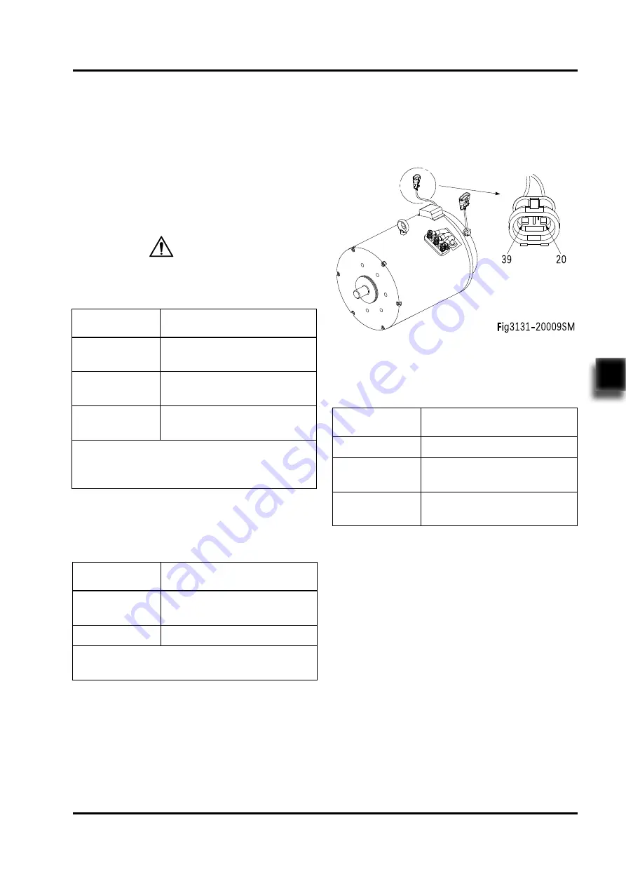
Temperature Sensor
Temperature sensor is used to monitor motor
temperature.
Measure the resistance between pin connector
(39#) and (20#) with a multimeter to identify if
the temperature sensor is normal.
As shown in the following table:
Resistance
Measurement
Judgment
With readings
Normal
0 Ω
Sensor short circuit
(replace the motor)
∞
Ω
Sensor open circuit
(replace the motor)
Checking
Speed Encoder
Speed encoder is used to detect the speed
of the motor and covert the speed into fixed
signals.
-
Check if the motor encoder and the appear-
ance of cables are in good condition, and if
the plug connection is secure.
-
Remove the speed encoder and check its
sensing surface for wear.
5.2.3 Checking and Testing
U, V, W Terminals
-
Identify if the motor windings are normal
through measuring the resistance of U-V, V-W,
and U-W respectively, if there is short circuit
or breakage;
as shown in the following table:
Due to the small size of windings, when measu-
ring with a multimeter, put it on a low resistance
range.
Resistance
Measurement
Judgment
With readings,
but very low
Normal
*
0 Ω
Winding internal short circuit
(replace the motor)
∞
Ω
Winding internal open circuit
(replace the motor)
*
The difference between the resistance values
measured at U-V, V-W and U-W shall not be
greater than 2%.
CAUTION
-
Identify if there is leakage current through
measuring the resistance between U, V, W
and motor housing respectively.
as shown in the following table:
Resistance
Measurement
Judgment
0 Ω
Leakage current
(replace the motor)
∞
Ω
Normal
*
*
For normal motor, U, V and W terminals are
insulated from motor housing.
Summary of Contents for CPD30L1-B
Page 1: ...Service Manual Electric Forklift Truck CPD30 35L1 B CPD30 35L1 S ...
Page 2: ...Service Manual Electric Forklift Truck CPD30 35L1 B CPD30 35L1 S ...
Page 13: ...1 1 1 INFORMATION SPECIFICATIONS ...
Page 14: ...2 NOTE ...
Page 20: ...REV 05 2020 INFORMATION SPECIFICATIONS 1 8 ...
Page 21: ...9 2 2 MAINTENANCE ...
Page 22: ...10 NOTE ...
Page 31: ...19 3 3 STRUCTURE FUNCTIONS ...
Page 32: ...20 NOTE ...
Page 39: ...27 4 4 CHASSIS SYSTEM ...
Page 40: ...28 NOTE ...
Page 46: ...34 REV 05 2020 CHASSIS SYSTEM 4 ...
Page 47: ...35 5 5 DRIVE SYSTEM ...
Page 48: ...36 NOTE ...
Page 49: ...37 REV 05 2020 DRIVE SYSTEM 5 Drive System No Name 1 Drive Wheel 2 Gearbox 3 Drive Motor ...
Page 55: ...43 REV 05 2020 DRIVE SYSTEM 5 For CPD30 35L1 S see Fig3131 20012SM ...
Page 61: ...49 6 6 OPERATING SYSTEM ...
Page 62: ...50 NOTE ...
Page 68: ...56 REV 05 2020 OPERATING SYSTEM 6 For CPD30 35L1 S Fig3131 30008SM ...
Page 80: ...68 REV 05 2020 OPERATING SYSTEM 6 ...
Page 81: ...69 7 7 HYDRAULIC SYSTEM ...
Page 82: ...70 NOTE ...
Page 84: ...72 REV 05 2020 HYDRAULIC SYSTEM 7 7 1 1 Hydraulic Schematic Diagram ...
Page 89: ...77 REV 05 2020 HYDRAULIC SYSTEM 7 ...
Page 101: ...89 8 8 STEERING SYSTEM ...
Page 102: ...90 NOTE ...
Page 107: ...REV 05 2020 STEERING SYSYTEM 8 95 ...
Page 109: ...97 9 9 ELECTRICAL SYSTEM ...
Page 110: ...98 NOTE ...
Page 183: ...REV 05 2020 ELECTRICAL SYSTEM 9 171 9 13 Electrical Schematic Diagrams CPD30 35L1 B ...
Page 185: ...REV 05 2020 ELECTRICAL SYSTEM 9 173 9 15 Wiring Harness and Connectors CPD30 35L1 B ...
Page 186: ...REV 05 2020 ELECTRICAL SYSTEM 9 174 9 16 Wiring Harness and Connectors CPD30 35L1 S ...
Page 187: ...175 10 10 TROUBLESHOOTING ...
Page 188: ...176 NOTE ...
Page 194: ...REV 05 2020 TROUBLESHOOTING 10 182 ...
Page 195: ...183 APPENDIX ...
Page 196: ...184 NOTE ...
Page 197: ...185 A A SERVICE MANUAL MAST ...
Page 198: ...186 NOTE ...
Page 213: ...201 REV 05 2020 SERVICE MANUAL MAST A ...
Page 220: ...208 REV 05 2020 SERVICE MANUAL MAST A ...
Page 226: ...214 REV 05 2020 SERVICE MANUAL MAST A ...
Page 227: ...215 B B SERVICE MANUAL BATTERY ...
Page 228: ...216 NOTE ...
Page 232: ...220 C C SCHEDULE ...
Page 233: ...221 ...
Page 235: ......


