background image

Quad User Modules 

User Manual

80-14001000-03

2–14

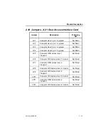
2.11  Jumpers - X.21 Rear Backup Interface Card

User 1 & 2 and Link 1 & 2 are on the bottom pcb, User 3 & 4 and Link 3
& 4 are on the top pcb.  The links are in the same relative positions on
both cards.

Jumper

Description

F=Factory

Set

JP1

Connects User 1 or 3  pin 1 to ground

Not fitted

JP2

Connects Link 1 or 3 pin 1 to ground

Not fitted

JP3

Connects User 2 or 4 pin 1 to ground

Not fitted

JP4

Connects Link 2 or 4 pin 1 to ground

Not fitted

JP5

Not used

JP6

Connects 120R across Link 1 & 3 Clock

Not fitted

JP7

Connects 120R across Link 1 & 3 Indicate

Not fitted

JP8

Connects 120R across Link 1 & 3 RxD

Not fitted

JP9

Connects 120R across User 1 & 3 TxD

Not fitted

JP10

Connects 120R across User 1 & 3 Control

Not fitted

JP11

Connects 120R across Link 2 & 4 RxD

Not fitted

JP12

Connects 120R across Link 2 & 4 Indicate

Not fitted

JP13

Connects 120R across Link 2 & 4 Clock

Not fitted

JP14

Connects 120R across User 2 & 4 TxD

Not fitted

JP15

Connects 120R across User 2 & 4 Control

Not fitted

Summary of Contents for SBUQHS/QHB

Page 1: ...ivemere Ltd Cabletron Systems Ltd Fivemere House Network House 161 High Street Newbury Business Park Aldershot London Road Newbury Hampshire England Berkshire England GU11 1TT RG13 2PZ Telephone 44 0...

Page 2: ...om PLC Hull City Council and Mercury Communications and is subject to the conditions set out in these instructions for use Refer to the SBU Systems User Manual for safety compliance and precautions Pa...

Page 3: ...r Modules User Manual 80 14001000 03 iii History Sheet 80 14001000 01 V1 00 software 24 June 1996 80 14001000 02 Cabletron Systems Edition 02 July 1997 80 14001000 03 Addition of Backup Modules 11 Aug...

Page 4: ...SHELF POWER LOADING 2 5 2 3 FUNCTIONAL DESCRIPTION 2 6 2 3 1 SBUQLS 2 6 2 3 2 SBUQHS 2 6 2 4 SBUQLB AND SBUQHB 2 7 2 4 1 CIRCUIT FAILURE 2 7 2 4 2 CIRCUIT RESTORAL 2 7 2 5 TALKWIRE 2 7 2 6 USER LED I...

Page 5: ...ERFACE SBUQHS QHB 4 1 4 1 MENU DESCRIPTION 4 1 4 2 TOP LEVEL MENU 4 2 4 3 OPERATION MENU PORT 4 2 4 4 CONFIGURATION MENU 4 2 4 4 1 ALARMS MENU 4 3 4 4 2 USER PORT MENU 4 5 4 4 3 EDIT STORE MENUS 4 6 4...

Page 6: ...G COMMANDS 6 3 6 2 5 MISCELLANEOUS COMMANDS 6 3 7 C DTR ORIGINATE CALL CONTROL 7 1 7 1 I DSR 7 2 7 2 C DTR 7 2 7 3 RI 7 2 8 X 21 CALL CONTROL SBUQLS QLB 8 1 8 1 COMMAND FORMAT 8 1 8 2 COMMANDS 8 1 8 3...

Page 7: ...ER AND LINK CABLES 10 4 11 GLOSSARY OF TERMS 11 1 12 MENU DIAGRAMS 12 1 12 1 SBUQLS 12 2 12 1 1 SBUQLS CONFIGURATION MENU 12 2 12 1 2 SBUQLS OPERATION MENU 12 4 12 2 SBUQHS 12 5 12 2 1 SBUQHS OPERATIO...

Page 8: ...introduction to the cards and the Primary Rate system Chapter 2 provides information on the Quad User Modules Chapter 3 to 8 provide detailed information on configuration and operation Please refer t...

Page 9: ...backup applications For cards other than the Quad User Modules used in the Shelf System please see the relevant manual Management is provided via the Manager Card SBUGSM or SBULSM in the system Please...

Page 10: ...panel buttons Storage of 100 ISDN telephone numbers for each of the ports including a sub address field for each Automatic fault detection on the Digital Leased Circuits DLCs Fully automatic or manua...

Page 11: ...nager card when accessed via Talkwire you will be prompted for a password the Manager card password for the shelf in which the interrogated unit resides before being given access to the unit Alarm mes...

Page 12: ...ports provide automatic backup and restoral in the event of DLC failure Asynchronous rate adapted speeds are provided up to 38k4bit s or synchronous rate adapted speeds up to 64kbit s All the SBUQLS...

Page 13: ...the master port of a Rackmount Cabletron Systems Generic Port Sharer or a standalone Cabletron Systems PSV4 1 Please refer to the manual on the SBU Systems for details of how to set this and other pa...

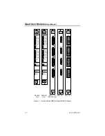
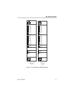
Page 14: ...1 Introduction The Modules use a discrete front card interface changes being accommodated by changing the rear interface cards which are common to both front card types Figure 1 Figure 2 and Figure 3...

Page 15: ...S CTS DSR RI DIAL 1 DIAL 2 Connected User 1 2 User 3 4 TalkWire Alert User 3 4 T TxD R RxD C DTR I DCR S TxC RxC RTS CTS DSR RI DIAL 3 DIAL 4 SBU Test Bit Err SBUQHS Front User 1 2 T TxD R RxD C DTR I...

Page 16: ...D R RxD C DTR I DCD S TxC RxC RTS CTS DSR RI BACKUP 3 BACKUP 4 SBU Test Bit Error QLB User 1 2 T TxD R RxD C DTR I DCD S TxC RxC RTS CTS DSR RI BACKUP 1 BACKUP 2 Backup User 1 2 User 3 4 TalkW ire Ale...

Page 17: ...Rear X 21 Rear V 24 SBUQLB only User 1 Link 1 User 2 Link 2 User 3 Link 3 User 4 Link 4 User 1 Link 1 User 2 Link 2 User 3 Link 3 User 4 Link 4 Link 1 User 2 Link 2 User 1 Rear V 35 Link 3 User 4 Link...

Page 18: ...0 SBUQLB V24 250 620 50 SBUQHB X21 2 830 600 0 SBUQHB V35 2 780 880 50 SBUQHB V24 2 250 620 50 When installing modules into the Shelf the installation engineer must ensure that the shelf power supplie...

Page 19: ...provided for the four user ports each capable of aggregating together up to thirty 64kbit s ISDN B channels to provide an N x 64 kbit s stream using either all B channels for Mode 1 or N 1 B channels...

Page 20: ...y of the following conditions are detected No data is received from the DLC No clock is detected from the DLC The I DSR signal from the DLC goes to the OFF condition The C DTR signal from the User DTE...

Page 21: ...the respective user port is connected to an ISDN B channel Access Modules only All Port Backup LED s ON when the respective user port is backed up to an ISDN B channel Backup Modules only Talkwire Ye...

Page 22: ...ided by changing the rear interface cards all four ports are always of the same type In all cases all User ports operate as DCEs and Link ports operate as DTEs The SBUQLS and SBUQLB operate at the dat...

Page 23: ...t has been connected or disconnected ALERT Channel status 1 Port disconnected no B channels in use ALERT Channel status 2 Port disconnected one or more B channels in use E g a Talkwire call or call se...

Page 24: ...CD loss DCD interruptions TalkWire ALERT Performing backup When a backup call is being made ALERT Performing restore When a circuit is being restored Table 3 ALERTs Generated by the Quad User Modules...

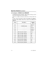
Page 25: ...s are used for both SBUQLS and SBUQHS likewise the same Backup rear cards are used for the SBUQLB and SBUQHB Jumper Description F Factory Set JP1 Clock post JP2 Watchdog enable IN F JP3 Not used JP4 N...

Page 26: ...4 Connects User 4 pin 1 to ground Not fitted JP5 Connects 120R across User 1 Transmit Not fitted JP6 Connects 120R across User 1 Control Not fitted JP7 Connects 120R across User 2 Transmit Not fitted...

Page 27: ...1 to ground Not fitted JP4 Connects Link 2 or 4 pin 1 to ground Not fitted JP5 Not used JP6 Connects 120R across Link 1 3 Clock Not fitted JP7 Connects 120R across Link 1 3 Indicate Not fitted JP8 Con...

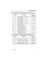
Page 28: ...and pin B Not fitted JP5 Connects 120R across User 1 Transmit pins P and S Not fitted JP6 Connects 120R across User 2 Transmit pins P and S Not fitted JP7 Connects 120R across User 3 Transmit pins P...

Page 29: ...tch on the front pcb Pole 1 is reserved for internal use Pole 3 performs a factory default when it is ON Having defaulted the card pole 3 must then be turned OFF to enable the card to operate The card...

Page 30: ...has port after it then the port number 1 2 3 or 4 is displayed in the prompt The following commands have a special meaning and are executed with single keystrokes 1 Selects port 1 2 Selects port 2 3...

Page 31: ...in the number store and then dials the number contained in it D LIST ALL NUMBERS Lists all the numbers in the number store E ANSWER Answers the incoming call F HANGUP Clears the call G TALKWIRE Provid...

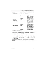
Page 32: ...a bit error test Lights the error LED briefly for every bit error received B OFF F Terminates the test 3 4 Configuration menu The F in the text represents the factory default setting The unit can be f...

Page 33: ...2 Port disconnected one or more B channels in use E g a Talkwire call ALERT Channel status 3 Port connected one or more B Channels in use B DISABLED This alert is disabled B ALERT DIAL A ENABLED F Se...

Page 34: ...nn n is the source of the call B DISABLED This alert is disabled D ALERT ISDN VERIFY A ENABLED F Sends an ALERT for either pass or fail of the daily ISDNTEST B DISABLED This alert is disabled E ALERT...

Page 35: ...3 Current store for port 3 held in non volatile memory D PORT 4 Current store for port 4 held in non volatile memory E STORE 1 Factory default configuration from this store is copied to ports 1 4 whe...

Page 36: ...er port A DTR ORIGINATE F 2 DTR call control as originating calls when C DTR goes ON B DTR ANSWER DTR call control as answering calls with C DTR ON This setting overrides the ANSWER MAN AUTO setting C...

Page 37: ...s 8 bit operation B ASYNC Asynchronous operation A DATA BITS The number of data bits in each asynchronous character A 5 BIT B 6 BIT C 7 BIT D 8 BIT F B PARITY Selections for the parity checking of eac...

Page 38: ...L SWITCHED 56k Synchronous only This must be set for calls to USA where 7 bit structured 56K networks are used D USER RATE NOTIFICATION A DISABLED F User rate information not sent B ENABLED Enables th...

Page 39: ...UQLS QLB B FORCED ON Output is forced on from the SBUQLS QLB C FORCED OFF Output is forced off from the SBUQLS QLB H CTS Selects the required CTS output A NORMAL F Output comes from the SBUQLS QLB B F...

Page 40: ...n incoming call automatically B CLID Answers the call only if the originating number matches a number in the CLID store Otherwise the call is rejected C MANUAL Awaits the user to command the SBUQLS QL...

Page 41: ...een gained then the call is disconnected at both ends B T W AUTO CONNECT As for T W CONNECT but if Talkwire is unsuccessful the user port is still connected after expiry of the Talkwire and Connect ti...

Page 42: ...ecting the user T W AUTO CONNECT D CONNECT TIMER ENTER CONNECT TIMEOUT VALUE 0 999s Default 0s The time delay after Online or Talkwire Active before the user port is connected E V 25bis DTR BUSY OUT W...

Page 43: ...red C DATA LOSS TIMER Time over which loss of data needs to occur to sense DLC loss B CLOCK LOSS A ENABLED Monitors DLC clock for activity B DISABLED F Not monitored C CLOCK LOSS TIMER Time over which...

Page 44: ...estore menu A RESTORE DELAY TIMER Time during which DLC must be continuously detected as being available for use before automatic restoral is initiated B LEASED CIRCUIT A DISABLED Automatic restoral i...

Page 45: ...ait 1 minute after configuration to ensure erroneous backup does not occur outside the window times that have been set Erroneous backup can occur due to delay in the system with recognising changed ti...

Page 46: ...up a window A MONDAY B TUESDAY C WEDNESDAY D THURSDAY E FRIDAY F SATURDAY G SUNDAY Any of these selections cause a further menu to be presented as follows A SLOT 1 B SLOT 2 C SLOT 3 D SLOT 4 Once the...

Page 47: ...es 3 4 3 7 ISDNTEST menu A ENABLED B DISABLED F Enables the daily test call over the ISDN to check the connection C MANUAL Effects a test call immediately without affecting any daily set time D SET TI...

Page 48: ...store for port 1 held in non volatile memory B PORT 2 Current store for port 2 held in non volatile memory C PORT 3 Current store for port 3 held in non volatile memory D PORT 4 Current store for port...

Page 49: ...menus are starred as unavailable on the terminal screen Refer to the relevant manual on the B channel provider module e g SBUPRI for details of how to set these MSN SUB ADDRESS C DIAL NUMBER A STORE...

Page 50: ...locations 3 6 Cyclic Dialling Store A ATTEMPTS PER NUMBER ENTER ATTEMPTS 1 999 Default 1 This is the number of call attempts at each number before moving to the next number in the dial store B DELAY...

Page 51: ...this section also refer to the SBUQHB See section 12 for diagrams of the menu structure If a menu has port after it then the port number 1 2 3 or 4 is displayed in the prompt The following commands ha...

Page 52: ...ed in it D LIST ALL NUMBERS Lists all the numbers in the number store E ANSWER Answers the incoming call F HANGUP Clears the call 4 4 Configuration menu The F in the text represents the factory defaul...

Page 53: ...s ALERT Channel status 1 Port disconnected no B channels in use ALERT Channel status 2 Port disconnected B channel in use E g additional calls for channel aggregation ALERT Channel status 3 Port conne...

Page 54: ...NSUFFICIENT B CHANNELS A ENABLED F Sends an alert indicating that a call attempt failed due to an insufficient number of B Channels being available The alert message is ALERT Insufficient B Channels B...

Page 55: ...n of menu sub options see section 4 4 3 onwards A EDIT STORE A PORT 1 Current store for port 1 held in non volatile memory B PORT 2 Current store for port 2 held in non volatile memory C PORT 3 Curren...

Page 56: ...ort A DTR ORIGINATE F 4 DTR call control as originating calls when C DTR goes ON B DTR ANSWER DTR call control as answering calls when C DTR goes ON This setting overrides the ANSWER MAN AUTO setting...

Page 57: ...input should be A NORMAL F Input comes from the DTE B FORCED ON Input is forced on in SBUQHS C FORCED OFF Input is forced off in SBUQHS F I DCD Selects what the DCD or I output should be A NORMAL F Ou...

Page 58: ...nput is forced on in SBUQHS C FORCED OFF Input is forced off in SBUQHS J LAL CONTROL Selects if the loop pin on the SBUQHS is enabled pin L on V 35 rear interface card A DISABLED F Disables the loop p...

Page 59: ...LED Monitors DLC Received data for activity B DISABLED F Not monitored C DATA LOSS TIMER Time over which loss of data needs to occur to sense DLC loss B CLOCK LOSS A ENABLED Monitors DLC clock for act...

Page 60: ...A ENABLED C DTR must be ON for auto backup to occur when DLC loss is detected B DISABLED F Ignores the state of C DTR for auto backup 4 4 3 5 Restore menu A RESTORE DELAY TIMER Time during which DLC m...

Page 61: ...is necessary to wait 1 minute after configuration to ensure erroneous backup does not occur outside the window times that have been set Erroneous backup can occur due to delay in the system with reco...

Page 62: ...A SLOT 1 B SLOT 2 C SLOT 3 D SLOT 4 Once the slot number has been selected you are prompted for the Window start and end times Please enter the Start and End Times hh mm hh mm This must be terminated...

Page 63: ...call over the ISDN to check the connection C MANUAL Effects a test call immediately without affecting any daily set time D SET TIME You are prompted to set a daily time for the test see below When opt...

Page 64: ...n volatile memory C PORT 3 Current store for port 3 held in non volatile memory D PORT 4 Current store for port 4 held in non volatile memory E STORE 1 Factory default configuration copied to all four...

Page 65: ...r from a specified store C LIST DIAL NUMBER Lists the dial number specified from a particular location D LIST ALL NUMBERS Lists all the dial numbers in the store D CLID A STORE CLID NUMBER Stores a CL...

Page 66: ...the number of call attempts at each number before moving to the next number in the dial store B DELAY AFTER ATTEMPT ENTER DELAY BETWEEN ATTEMPTS 0 999 Default 3 Delay in seconds between each attempt C...

Page 67: ...the screen so you will only see the SBUQLS QLB s responses to the command ASYNC Used when the user port is in asynchronous mode Message format MESSAGE CR LF The new line function may sometimes be enc...

Page 68: ...mber is not used by the SBUQLS QLB CRS address Dial number stored at specified address CFINS Number is not stored or address is not valid All the above commands can have the responses VAL Number is be...

Page 69: ...nted for UK use RLD List delayed numbers LSD Not implemented for UK use RLI List ID number LSI ID number Note the ID number is not used by the SBUQLS QLB 5 5 ANSWERING commands DIC Disregard incoming...

Page 70: ...T Tone dialling Not implemented Flash Not implemented Presentation Presentation NOTE All the above characters which are not implemented or are presentation will be decoded but will be ignored as no ac...

Page 71: ...y the command menus 5 9 Control signals required The control signals follow the V 25bis specifications for the establishment of the call but can be overridden as configured from the command menus 103...

Page 72: ...s e g ATD 123456789 CR All spaces after AT will be ignored and the command must end with a carriage return When a number is expected and not returned then it defaults to zero Commands unknown to the S...

Page 73: ...played in the directory but are not dialled Subaddress e g 1234567 888 Dials the number 1234567 and specifies subaddress 888 Pause Not implemented P Pulse dialling Not implemented T Tone dialling Not...

Page 74: ...S QLB to answer an incoming call 6 2 5 Miscellaneous Commands ATHn On Off Hook n 0 Forces SBUQLS QLB to disconnect from the ISDN No other n value is valid ATO Forces the SBUQLS QLB back to data mode f...

Page 75: ...5 circuit 108 1 or in X 21 control line C This provides the facility of setting up a call without exchanging messages The number to be dialled is stored in the Quad User Modules by using the command m...

Page 76: ...TR while in the data transfer mode 7 2 C DTR C DTR will be turned on by the DTE i To instruct the Quad User Module to dial the pre recorded number over the ISDN as the calling party ii To instruct the...

Page 77: ...below Any further information on the following can be obtained from the full X 21 specification Commands will not be echoed back to the screen so you will only see the SBUQLS QLB s responses to the co...

Page 78: ...lete the number from store 0 The DTE is able to amend the designated address by performing a cancellation procedure followed by a registration procedure Store number 66 1 address number Stores the num...

Page 79: ...s back to the DTE 01 TERMINAL CALLED 20 NO CONNECTION 21 NUMBER BUSY 22 SELECTION SIGNALS PROCEDURE ERROR 23 SELECTION SIGNALS TRANSMISSION ERROR 42 CHANGED NUMBER 43 NOT OBTAINABLE 44 OUT OF ORDER 45...

Page 80: ...ng of up to 20 characters A character may be a digit 0 9 subaddress A string consisting of up to 20 characters A character may be a digit 0 9 or any character from the alphabet a z upper or lower case...

Page 81: ...all female 15 way D type Link connectors for backup modules are male 15 way D type The pin assignments are as follows Pin No Circuit No Signal Name 1 Ground Chassis Earth 8 G Signal Ground Chassis Ea...

Page 82: ...rcuit No Signal Name A 101 Signal Ground Chassis Earth B 102 Signal Ground Chassis Earth P 103A Transmit Data A S 103B Transmit Data B R 104A Receive Data A T 104B Receive Data B Y 114A Transmit Clock...

Page 83: ...ssis Earth 2 103 Transmit Data 3 104 Receive Data 4 105 Request To Send 5 106 Clear To Send 6 107 Data Set Ready 7 102 Signal Ground Chassis Earth 8 109 Data Carrier Detect 15 114 Transmit Clock 17 11...

Page 84: ...les These can be made according to the specifications attached or alternatively they are available from your equipment supplier The specifications of the these cables assume Male presentation at the D...

Page 85: ...ed for connection to both the User and Link ports with an X 21 rear interface Access or Backup card should be a straight pin to pin cable with 15 way D connectors Female D Type Male D Type 1 2 9 3 10...

Page 86: ...card should be a straight pin to pin cable with 34 way MRAC connectors Female 34 Way MRAC Male 34 Way MRAC A B P S R T C D E H F Y AA V X A B P S R T C D E H F Y AA V X Cable CAB0035 is available for...

Page 87: ...e required for connection to both the User and Link ports of a V 24 rear Access or Backup interface card should be a straight pin to pin cable with 25 way D connectors Female 25 Way D Male 25 Way D 1...

Page 88: ...agement Module SBULSM LAN Shelf Management Module SBU NM Cabletron Systems Cyber Backup proprietary network management system SBUPRI Primary Rate Interface Module SBUQHB Quad High Speed Backup Module...

Page 89: ...odules User Manual 80 14001000 03 11 2 Note that SmartSWITCH Backup SBU products were previously known as Cyberbackup CBU Therefore all references in product manuals to SBU products equally apply to C...

Page 90: ...HS QHB there is a Configuration and an Operation menu block diagram The Configuration diagrams show the configuration menu structure Although there are several levels to this those on the right hand p...

Page 91: ...Quad User Modules User Manual 80 14001000 03 12 2 12 1 SBUQLS 12 1 1 SBUQLS QHB Configuration Menu...

Page 92: ...Menu Diagrams 80 14001000 03 12 3...

Page 93: ...Quad User Modules User Manual 80 14001000 03 12 4 12 1 2 SBUQLS QLB Operation Menu...

Page 94: ...Menu Diagrams 80 14001000 03 12 5 12 2 SBUQHS 12 2 1 SBUQHS QHB Operation Menu...

Page 95: ...Quad User Modules User Manual 80 14001000 03 12 6 12 2 2 SBUQHS QHB Configuration Menu...

Page 96: ...Menu Diagrams 80 14001000 03 12 7...

Reviews: