017-220-J0 Rev C
58
9.6 Alpha UPS Monitor Interface: Communication via USB
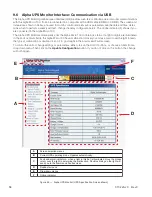
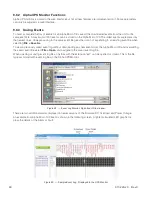
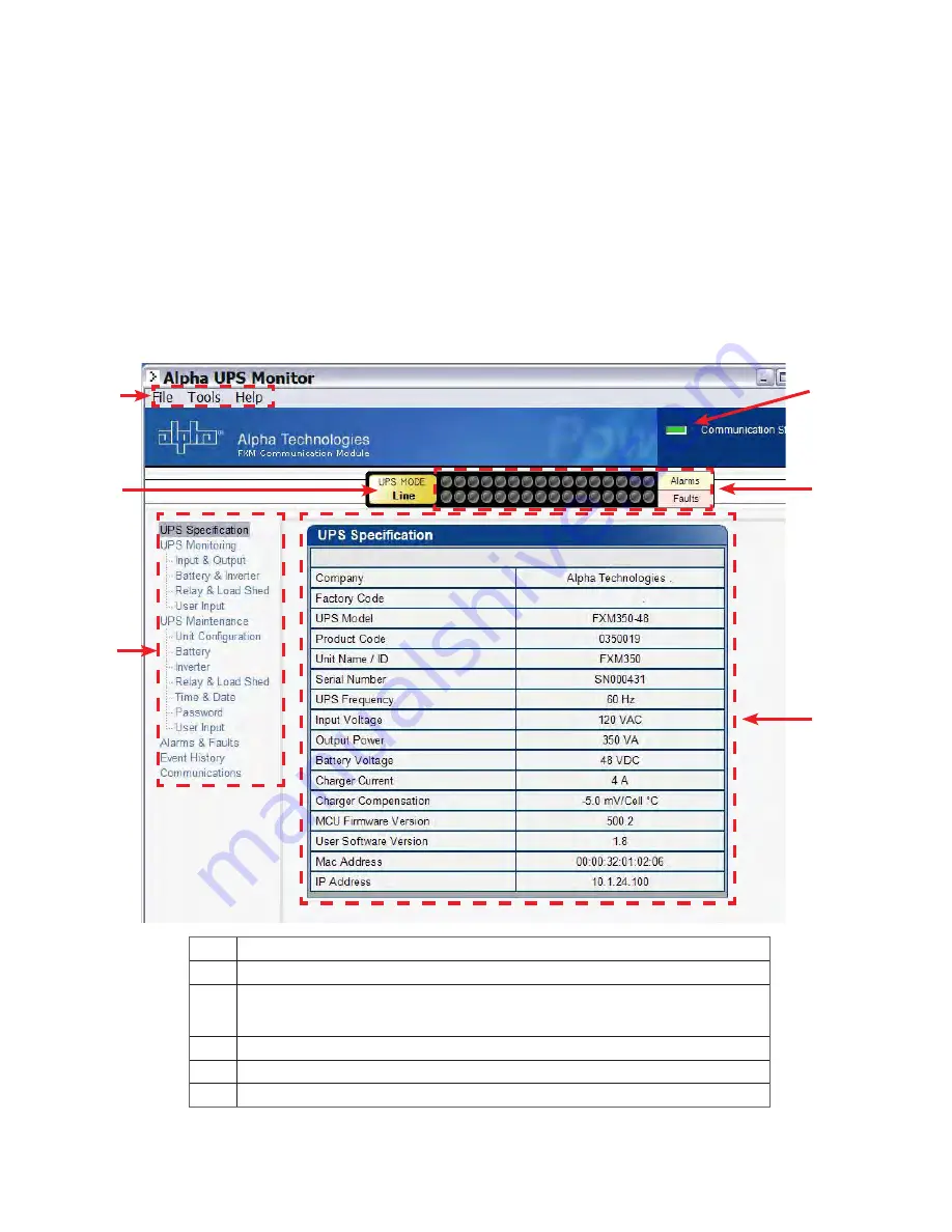
The Alpha UPS Monitor graphical user interface (GUI) provides web-like or Windows-like computer communications
with the Alpha Micro 100. It can be connected to a computer with a USB cable (USB-A to USB-B). The screen and
its features, shown in below, are used to monitor, control and set various parameters like the date and time, deter-
mine when to perform a weekly self test, change the relay configurations, etc. The on line indicator (F) shows if you
are connected to the Alpha Micro 100
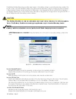
The Alpha UPS Monitor automatically polls the Alpha Micro 100 to obtain its status. If a light or lights are illuminated
in the Fault or Alarm fields, the Alpha Micro 100 has a malfunction. Hover your mouse cursor over the light to learn
the type of malfunction or double-click on it to go straight to the Alarms and Faults screen.
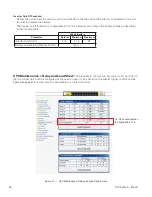
To control the unit or change settings or parameters, either click on the On/Off buttons, or choose an item from a
drop down menu. Then click on the
Update Configuration
button. If you do not click on this button, the change
will not happen.
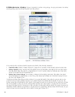
Figure 46 — Alpha UPS Monitor (UPS Specification Screen shown)
A
Screen selection menus
B
Current UPS operating mode. Updates automatically.
C
Fault and alarm indicators – when a light in this bar is illuminated, move the mouse
cursor over the light to determine the malfunction. Double-clicking on the light will
send you to the Alarms and Faults screen.
D
Readout screens
E
Drop-down menus
F
Online indicator
B
B
A
E
E
D
C
F
Summary of Contents for Alpha Micro 100
Page 1: ...Alpha Micro 100 UPS Technical Guide 017 220 J0 Effective 09 2020...
Page 2: ......
Page 36: ...35 017 220 J0 Rev C Figure 14 Web Interface Bulk Charging Menus...
Page 37: ...017 220 J0 Rev C 36 Figure 15 Web Interface Bulk Charging Menus...
Page 85: ......
Page 86: ......
Page 87: ......

