


3.4.4
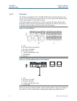
Terminating resistors
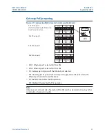
Three DIP switches are provided to enable various terminating resistors to the RS-485 data
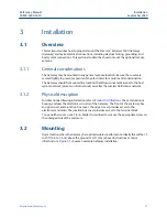
bus. The switches are found inside the electronics housing near the top center of the main
circuit board (
).
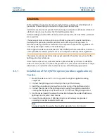
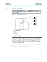
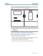
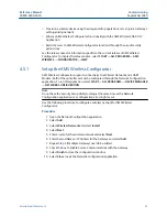
Figure 3-9: RS-485 Resistor DIP Switches
ON
K40
1
2
3
E
F
G
C
B
D
A
A. Main circuit board
B. Radio
C. Electronics
D. DIP switches
E. 470Ω pull-down resistor
F. 120Ω terminating resistor
G. 470Ω pull-up resistor
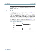
Switches 1 and 3 are connected to pull-up and pull down resistors. Switch 1 is for the Tx +
(A) line and Switch 3 is for the Rx – (B) line. These 470 Ω resistors are used to prevent noise
from being interpreted as valid communications during periods when no actual
communications are occurring. Only one set of pull-up and pull-down resistors should be
active on the RS-485 data bus at time.
Switch 2 is connected to a 120 Ω terminating resistor. This resistor is used to dampen
signal reflections on long cable runs. RS-485 specifications indicate that the data bus
should be terminated at both ends (
). However termination should only be
used with high data rates (above 115 kbps) and long cable runs.
Installation
Reference Manual
September 2020
00809-0200-4420
26
Emerson.com/Rosemount
Summary of Contents for Smart Wireless Gateway 1420
Page 1: ...Reference Manual 00809 0200 4420 Rev HE September 2020 Emerson Wireless 1420 Gateway ...
Page 34: ...Installation Reference Manual September 2020 00809 0200 4420 34 Emerson com Rosemount ...
Page 42: ...Commissioning Reference Manual September 2020 00809 0200 4420 42 Emerson com Rosemount ...
Page 62: ...Troubleshooting Reference Manual September 2020 00809 0200 4420 62 Emerson com Rosemount ...
Page 84: ...DeltaV Ready Reference Manual September 2020 00809 0200 4420 84 Emerson com Rosemount ...
Page 95: ...Reference Manual 00809 0200 4420 September 2020 Emerson com Rosemount 95 ...


