


Table 2-1: Default IP Addresses
(continued)
Gateway
PC/laptop
Subnet
Ethernet 2 (DeltaV Ready)
10.9.255.254
10.9.255.200
255.254.0.0
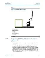
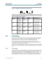
2.3.3
Connections and power
Physically connect the PC/laptop to the Gateway by connecting one end to the Ethernet
port on the back of the PC/laptop. Connect the other end to the Ethernet 1 port on the
Gateway.
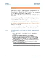
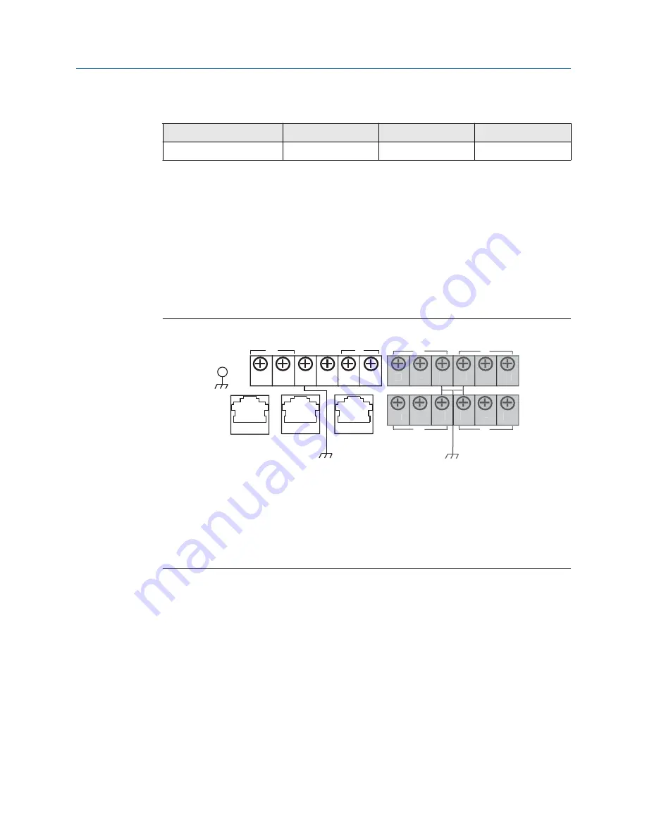
shows the standard terminal block diagram. Once the Gateway and
PC/laptop are connected, wire a 24 VDC (nominal) power supply with a capacity of at least
250 mA to the Gateway power input terminals.
Determining Gateway compatibility with Power over
Ethernet (PoE)
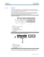
Figure 2-1: Legacy Gateway Terminal Block
+
+
+
+
+
-
-
-
-
-
A
B
S
S
S
S
S
A
B
C
D
E
F
G
G
G
G
A. Case
B. Ethernet 2 with power (covered)
C. Ethernet 2 (secondary)
D. Ethernet 1 (primary)
E. 24 VDC (nominal) power input
F. Serial Modbus
®
G. Not used
Reference Manual
Configuration
00809-0200-4420
September 2020
Emerson.com/Rosemount
9
Summary of Contents for Smart Wireless Gateway 1420
Page 1: ...Reference Manual 00809 0200 4420 Rev HE September 2020 Emerson Wireless 1420 Gateway ...
Page 34: ...Installation Reference Manual September 2020 00809 0200 4420 34 Emerson com Rosemount ...
Page 42: ...Commissioning Reference Manual September 2020 00809 0200 4420 42 Emerson com Rosemount ...
Page 62: ...Troubleshooting Reference Manual September 2020 00809 0200 4420 62 Emerson com Rosemount ...
Page 84: ...DeltaV Ready Reference Manual September 2020 00809 0200 4420 84 Emerson com Rosemount ...
Page 95: ...Reference Manual 00809 0200 4420 September 2020 Emerson com Rosemount 95 ...