58 Chapter 8 Option
Liebert APM 90 Integrated Modular UPS User Manual
Figure 8-3
~
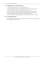
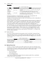
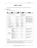
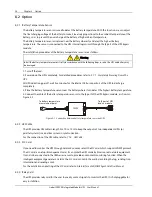
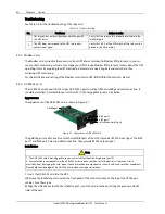
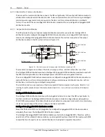
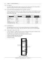
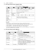
Figure 8-5 show the appearance and wiring principle of each cable.
DB25 male (pin-type)
13
25
12
24
11
23
10
22
9
21
8
20
7
19
6
18
5
17
4
16
3
15
2
14
1
K0_NO
K3_NO
K1_NO
K2_COM
K0_NC
K2_NO
K3_COM
K0_COM
K1_COM
Pin
K2_NC
K3_NC
K1_NC
DB25 male (pin-type)
Pin
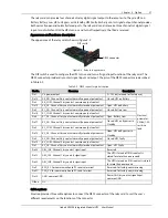
Figure 8-3
Appearance and wiring schematic of cable 1 (UFDRY21SL1)
DB25 male (pin-type)
13
25
12
24
11
23
10
22
9
21
8
20
7
19
6
18
5
17
4
16
3
15
2
14
1
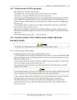
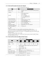
X14J7A plug (pin-type)
1
2
3
4
5
6
7
DB25 male (pin-type)
X14J7A plug (pin-type)
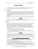
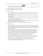
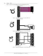
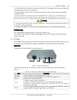
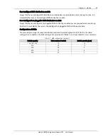
Figure 8-4 Appearance and wiring schematic of cable 2 (UFDRY21SL2)
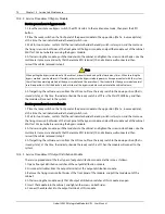
560 ohm/1W
DB25 male (pin-type)
13
25
12
24
11
23
10
22
9
21
8
20
7
19
6
18
5
17
4
16
3
15
2
14
1
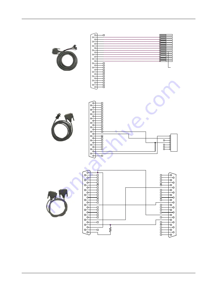
This end is labelled "UPS"
DB25 male (pin-type)
13
25
12
24
11
23
10
22
9
21
8
20
7
19
6
18
5
17
4
16
3
15
2
14
1
This end is labelled 'UPS'
DB25 male (pin-type)
DB25 male (pin-type)
560 ohm/1W
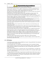
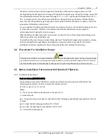
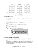
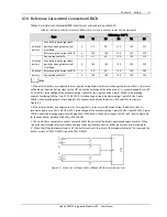
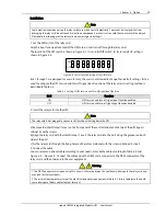
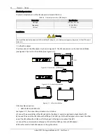
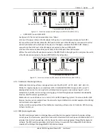
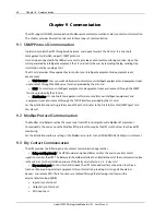
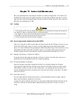
Figure 8-5 Appearance and wiring schematic of cable 3 (UFDRY21SL3)


