Chapter 3 Electrical Installation 23
Liebert APM 90 Integrated Modular UPS User Manual
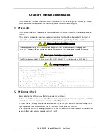
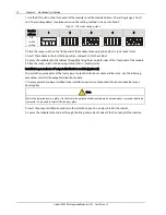
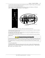
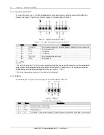
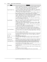
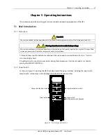
The connection between the BCB port and the BCB is shown in Figure 3-9.
OL
GND
FB
DRV
AUx-N.O.
AUx-N.O.
BCB
OL
GND
FB
DRV
J6
AUx-N.O.
AUx-N.O.
BCB
Figure 3-9
Connection between BCB port and BCB
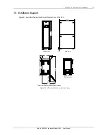
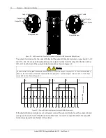
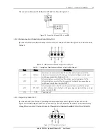
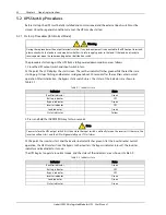
3.2.4
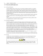
Maintenance Switch And Output Switch State Port
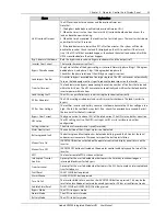
J9 is the maintenance switch and output switch state port. The port is shown in Figure 3-10 and described in
Table 3-5.
J9
GND
EXT-OUT
IN-S
EX
T
-Q3
Figure 3-10
Maintenance switch and output switch state port
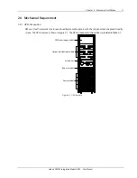
Table 3-5 Description of maintenance switch and output switch state port
Port
Name
Description
J9.1 EXT_Q3
External maintenance switch state. The auxiliary contact requirement of the
external maintenance switch: Auxiliary contact of external bypass closed upon
switch open; open when shorted with J9.4
J9.2 IN_S
Internal maintenance switch state. The auxiliary contact requirement of the
internal maintenance switch: Auxiliary contact of external bypass opened upon
switch open; closed when shorted with J9.4
J9.3 EXT_OUT
Internal output switch state. The auxiliary contact requirement of the output
switch: Auxiliary contact of output switch opened upon output switch open; closed
when shorted with J9.4
J9.4 GND
Power
ground
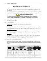
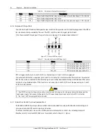
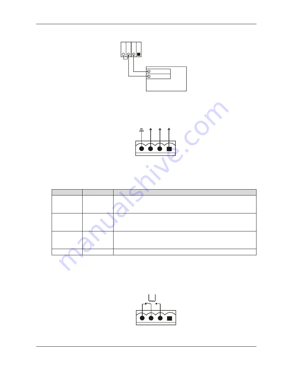
3.2.5
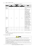
Output Dry Contact Port
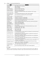
J5 is the output dry contact port, providing two relay output dry contact signals. The port is shown in
Figure 3-11 and described in Table 3-6. The shunt trip coil of the external air breaker can be driven directly
through this dry contact. The shunt trip coil of the external air breaker should be 250Vac/5A or 24Vdc/5A.
J5
BF
P-C
BF
P-S
BF
P-O
Figure 3-11
Output dry contact port


