20 Chapter 3 Electrical Installation
Liebert APM 90 Integrated Modular UPS User Manual
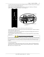
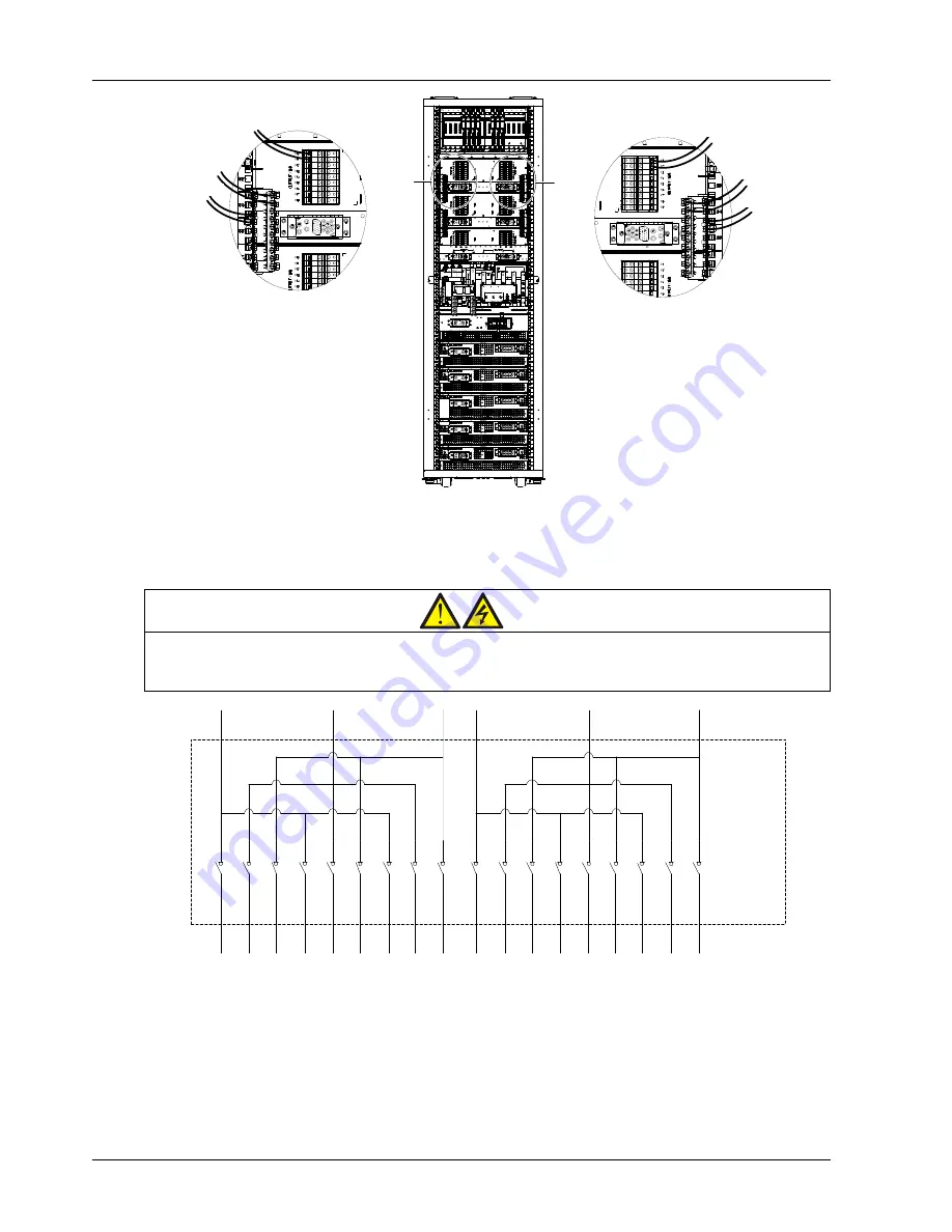
B
A
Output L cable
Output N cable
Output PE cable
B amplified view
A amplified view
Output L cable
Output N cable
Output PE cable
Output L cable
Output N cable
Output PE cable
B Amplified view
B
A
Output L cable
Output N cable
Output PE cable
A Amplified view
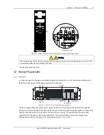
Figure 3-3
Cable connection to output terminals of output distribution module (back view)
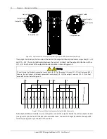
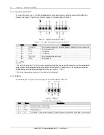
The output L terminals on the two sides at the back of the output distribution module are respectively X1
~
X9
and X10
~
X18. The control relationship between the output L terminals and the output distribution switches
QF1
~
QF18 on the front of the output distribution module is shown in Figure 3-4.
Warning
The total current of the loads connected to each phase (A, B, C) of the output L terminals X1
~
X9 shall not exceed 65A;
likewise, the total current of the loads connected to each phase (A, B, C) of the output L terminals X10
~
X19 shall not
exceed 65A either. Refer to Figure 3-4.
X1 X2
X3
X4
X5
X6
X7 X8
X9
X10 X11 X12 X13 X14 X15 X16 X17 X18
A
A
B
B
C
C
QF1 QF2 QF3 QF4 QF5 QF6 QF7 QF8 QF9 QF10 QF11 QF12 QF13 QF14
QF18
QF17
QF16
QF15
O
ut
pu
t d
is
tr
ib
ut
io
n
m
od
ul
e
Figure 3-4
Power distribution diagram of output distribution module
2) If output distribution modules are not configured, connect the output cables between the output terminals
(see Figure 3-5) on the front of the UPS cabinet and the loads. Connect the output PE cable to the output PE
terminal (see Figure 3-2) on the back of the cabinet.


