70 Chapter 10 Service And Maintenance
Liebert APM 90 Integrated Modular UPS User Manual
10.4.2
Service Procedures Of Bypass Module
Service procedures in bypass mode
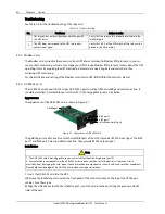
1. Close the maintenance bypass switch, the UPS transfers to the maintenance mode, then press the EPO
button.
2. Place the ready switch on the front panel of the power module to the up position (that is, in unready state),
at this time, the red indicator beside the ready switch is on.
3. Wait for two minutes, confirm that the red indicator beside the ready switch is always on, and then remove
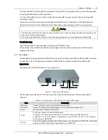
the fixing screws on both sides of the front panel of the bypass module, and pull the module out of the cabinet.
Wait for 10 minutes before servicing the bypass module.
4. After servicing the module, push the module into the cabinet, and tighten the screws on both sides. Use the
multimeter to measure and verify that the remote EPO terminal J10 and cable are well connected, then
reinsert the cables removed in step 3.
Note
When pulling the bypass module out of the cabinet, move it around and pull outward many times. When inserting the
bypass module, you should insert it forcibly, otherwise the bypass module poor may have poor contact with the system,
thus affect the normal operation of the bypass module and the overall unit. The standard for the bypass module normal
insertion position is that the brackets on both sides of the bypass module can be close to the cabinet column.
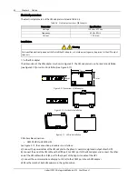
5. After getting the software version from the LCD menu, Place the ready switch to the down position (that is,
in ready state), at this time, the indicator beside the ready switch is off. Press the FAULT CLEAR key, and then
the module will connect to the system.
Service procedures in normal mode
1. Place the ready switch on the front panel of the power module to the up position (that is, in unready state),
at this time, the red indicator beside the ready switch is on.
2. Wait for two minutes, confirm that the red indicator beside the ready switch is always on, and then remove
the fixing screws on both sides of the front panel of the bypass module, and pull the module out of the cabinet.
Wait for 10 minutes before servicing the bypass module.
3. After servicing the module, push the module into the cabinet, and tighten the screws on both sides. Use the
multimeter to measure and verify that the remote EPO terminal J10 and cable are well connected, then
reinsert the cables removed in step 2.
4. After getting the software version from the LCD menu, Place the ready switch to the down position (that is,
in ready state), at this time, the indicator beside the ready switch is off. Then the module will connect to the
system.
10.4.3
Service Procedures Of Output Distribution Module
The service procedures of the four types of output distribution module are the same, as follows:
1. Open all output distribution switches of the output distribution module.
2. Disconnect all cables from the output terminals of this output distribution module.
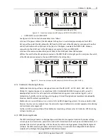
3. Remove the fixing screws on both sides of the front panel of the module, and pull the module out of the
cabinet.
4. After servicing the module, verify that all output distribution switches of this module are open.
5. Insert the module into the cabinet, and tighten the screws on both sides.
6. Connect the cables back to the output terminals of this module.

