60 Chapter 8 Option
Liebert APM 90 Integrated Modular UPS User Manual
Troubleshooting
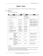
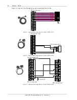
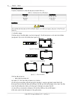
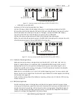
See Table 8-4 for the troubleshooting of the relay card.
Table 8-4
Troubleshooting
No.
Problems
Action to take
1
The dry contact output signal does not change with
the UPS status
Verify that the relay card is properly inserted into the
Intellislot port
2
The UPS does not respond to the UPS turn-on dry
contact input signal
Verify that bit 8 of the DIP switch of the relay card is
placed in the 'ON' position
8.2.5
Modbus Card
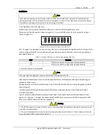
The Modbus card can realize the conversion from UPS internal protocol to Modbus RTU protocol, so you can
use your host monitoring software to manage your UPS through Modbus RTU protocol, to learn about the UPS
operating status by acquiring the UPS electrical parameter data, operating data and alarm data, thus
achieving UPS monitoring.
For the installation and setting of the Modbus card, refer to
UPS JBUS/MODBUS Adapter User Manual
.
8.2.6
UF-RS485 Card
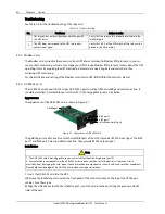
The UF-RS485 card converts RS232 signal to RS485 signal to realize UPS networking and communication. It
should be installed in an Intellislot port of the UPS. It is hot pluggable for easy installation.
Appearance
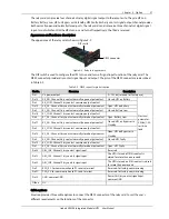
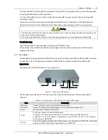
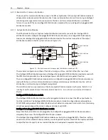
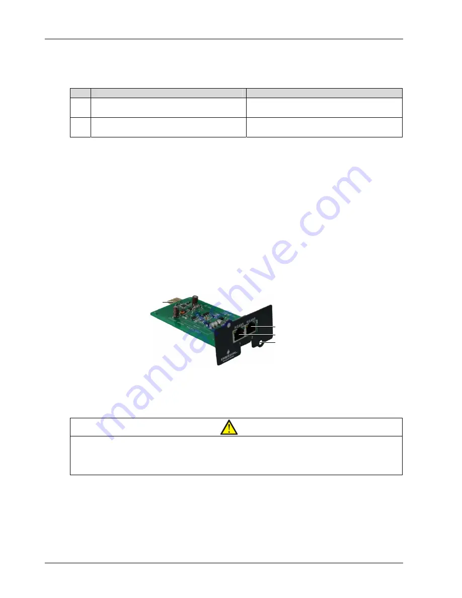
The appearance of the UF-RS485 card is shown in Figure 8-7.
Installation hole (2 pcs)
Goldfinger
RJ45 port 2
RJ45 port 1
RJ45 port 2
RJ45 port 1
Installation hole (2 pcs)
Goldfinger
Figure 8-7
Appearance of UF-RS485 card
The goldfinger is used for insertion into the Intellislot port of the UPS. It provides RS232 input signal. The RJ45
port 1 and RJ45 port 2 are in parallel connection. They provide RS485 output signal.
Installation
Note
1. The UF-RS485 card is hot-pluggable, so you can install it without shutting down the UPS.
2. Some electronic components on the UF-RS485 card are quite sensitive to static electricity. To prevent static
electricity from damaging the card, do not touch its electronic components or circuits with hands or other live objects.
Please hold the side edges of the UF-RS485 card when moving or installing it.
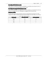
1. Insert the UF-RS485 card into the UPS.
a) Remove the Intellislot port cover on the front panel of the control module on the top of the UPS bypass
cabinet. Save the screws.
b) Align the UF-RS485 card with the Intellislot port, insert the card into the port along the grooves on both
sides of the port.

