


4 Chapter 1 Overview
Liebert APM 90 Integrated Modular UPS User Manual
Maintenance bypass
The UPS has a second bypass circuit, i.e. maintenance bypass, which provides a safe working environment for
the engineers to provide regular maintenance or repair to the UPS system and at the same time provide
unregulated mains supply to the loads. The maintenance bypass can be manually selected through the
maintenance switch. It can be disconnected by turning the switch to OFF.
1.2.4
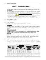
UPS Power Supply Switch Configuration
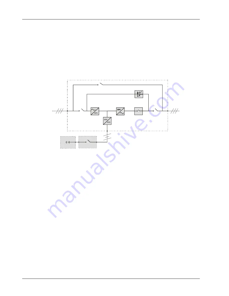
As shown in Figure 1-2, the main input power and bypass input power of the UPS are fed from the common
input switch Q1, and the UPS provides the maintenance switch Q2 and output switch Q3 as well.
During normal UPS operation, all power switches except for the maintenance switch Q2 should be closed.
Mains input
Input switch Q1
Rectifier
Inverter
Automatic
inverter switch
Output
switch Q3
UPS Output
Static switch
Maintenance switch Q2
Charger
Battery switch
Battery
Figure 1-2
UPS power supply switch configuration
1.2.5
BCB
The external battery must be connected to the UPS through a BCB. The BCB should provide over-current
protection, short circuit protection and automatic tripping functions. The BCB should be installed near the
battery.
1.3
Operation Mode
The UPS is an on-line, double-conversion, reverse-transfer UPS that permits operation in these modes:
Normal mode
Battery mode
Bypass mode
Maintenance mode (manual bypass)
Automatic restart mode
ECO mode
Dormancy mode
Frequency converter mode
Dual bus (LBS) system mode


