Chapter 8 Option 59
Liebert APM 90 Integrated Modular UPS User Manual
Installation
Note
Some electronic components on the relay card are sensitive to static electricity. To prevent static electricity from
damaging the relay card, do not touch its electronic components or circuits, also avoid their contact with live objects.
Please hold the side edges of the relay card when moving or installing it.
1. Set the DIP switch of the relay card.
Skip this step if you need not control the UPS turn-on and turn-off through the relay card.
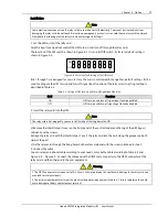
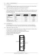
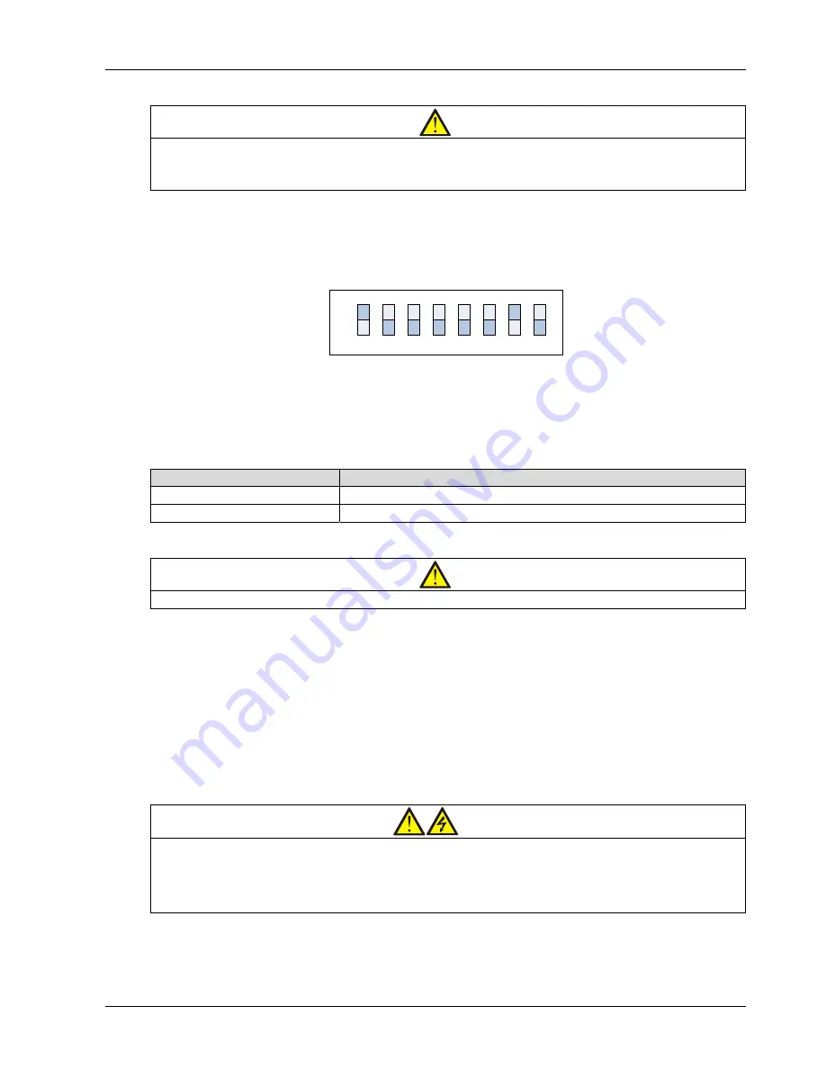
The location of the DIP switch is shown in Figure 8-2. It is an 8-bit DIP switch. Its factory default setting is
shown in Figure 8-6.
1
2
3
4
5
6
7
8
ON
OFF
Figure 8-6
Factory default setting of the DIP switch
Bits 1 through 7 are designed for use in factory, the user is not allowed to change their default settings. Bit 8 is
used to configure the UPS turn-on and turn-off signal input function of the relay card, its setting method is
described in Table 8-3.
Table 8-3
Setting of UPS turn-on and turn-off signal input function
Bit 8
Function
ON
UPS turn-on and turn-off signal input function enabled
OFF
UPS turn-on and turn-off signal input function disabled
2. Insert the relay card into the UPS.
Note
The relay card is hot-pluggable, you can install it without shutting down the UPS.
a) Remove the Intellislot port cover on the front panel of the control module on the top of the UPS bypass
cabinet. Save the screws.
b) Align the relay card with the Intellislot port, insert the relay card into the port along the grooves on both
sides of the port.
c) Fix the relay card through the fixing holes on the relay card panel with the screws obtained in step 1.
3. Connect the cable.
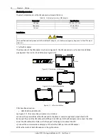
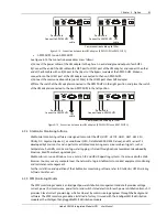
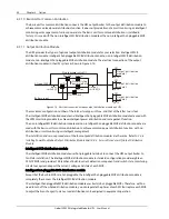
You can select an optional cable according to your needs, or make the cable according to Table 8-2 and
Figure 8-3
~
Figure 8-5. Connect the cable end with a DB25 male connector to the DB25 connector of the
relay card, and the other end to the user equipment.
Warning
1. The DB25 connector must connect to SELV circuit. Failure to observe this could cause damage to the relay card and
even lead to safety accidents.
2. The external equipment must meet the electrical parameter requirement in Table 8-2, failure to observe this could
cause damage to the dry contact output terminal.

