Chapter 8 Option 61
Liebert APM 90 Integrated Modular UPS User Manual
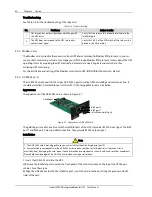
c) Fix the UF-RS485 card through the fixing holes on the UF-RS485 card panel with the screws obtained when
removing the Intellislot port cover previously.
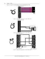
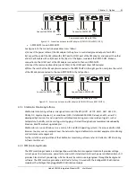
2. Connect the cable. Users can select a standard network cable in proper length as the connecting cable
according to needs.
a) Insert one end of the standard network cable into the RJ45 port 1 or RJ45 port 2 of the UF-RS485 card.
b) Insert the other end of the standard network cable to the corresponding port of the user equipment.
Warning
1. The RJ45 ports of the UF-RS485 card must connect to SELV circuit. Failure to observe this could cause damage to the
card and even result in safety accidents.
2. The connecting cable of the UF-RS485 card and the external equipment must be a double-end shielded cable.
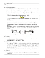
Troubleshooting
Fault: The UF-RS485 output signal does not change with the UPS status.
Action to take: Ensure that the UF-RS485 card is properly inserted into the Intellislot port and the cable is
properly connected.
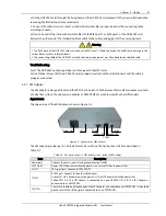
8.2.7
LBS Adapter
T
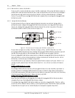
he LBS adapter is designed to extend the LBS function up to 150m between the two UPS modules or systems
of a dual bus system. The adapter also enables an APM 90 UPS to synchronize with other UPS models
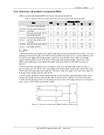
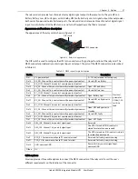
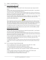
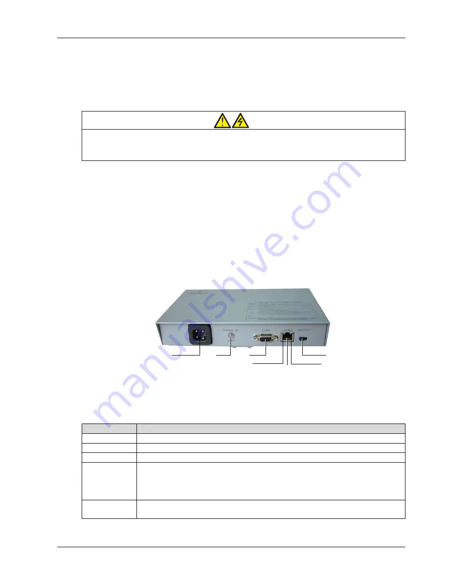
Appearance
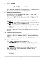
The appearance of the LBS adapter is shown in Figure 8-8.
Power port
Yellow LED
Green LED
LED1
COM1
Switch
COM2
Figure 8-8
Appearance of LBS adapter
The LBS adapter provides ports, LED indicators and a switch on the front panel, which are described in
Table 8-5.
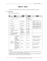
Table 8-5
Description of ports, LED indicators and switch of LBS adapter
Item
Description
Power port
Connect to phase A, neutral and ground of output of UPS
LED1 (red)
Power LED. It illuminates when the power is on, turns off when the power fails
COM1
LBS signal port. Connect to APM 90 UPS
COM2
RS485 port. Connect to the other LBS adapter.
Green LED. On: The communication power is OK; off: The communication power fails.
Yellow LED. On: The LBS adapter is connected to a non-APM 90 UPS; off: The LBS adapter is
connected to an APM 90 UPS
SWITCH
The switch should be placed to right if the LBS adapter is connected to an APM 90 UPS; it should be
placed to left if the LBS adapter is connected to a non-APM 90 UPS


