


Chapter 3 Electrical Installation 19
Liebert APM 90 Integrated Modular UPS User Manual
1. Verify that the external input switch and all internal power switches of the UPS are open. Post warning signs
on these switches to prevent inadvertent operation.
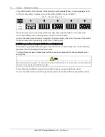
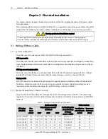
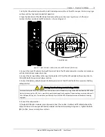
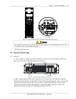
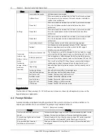
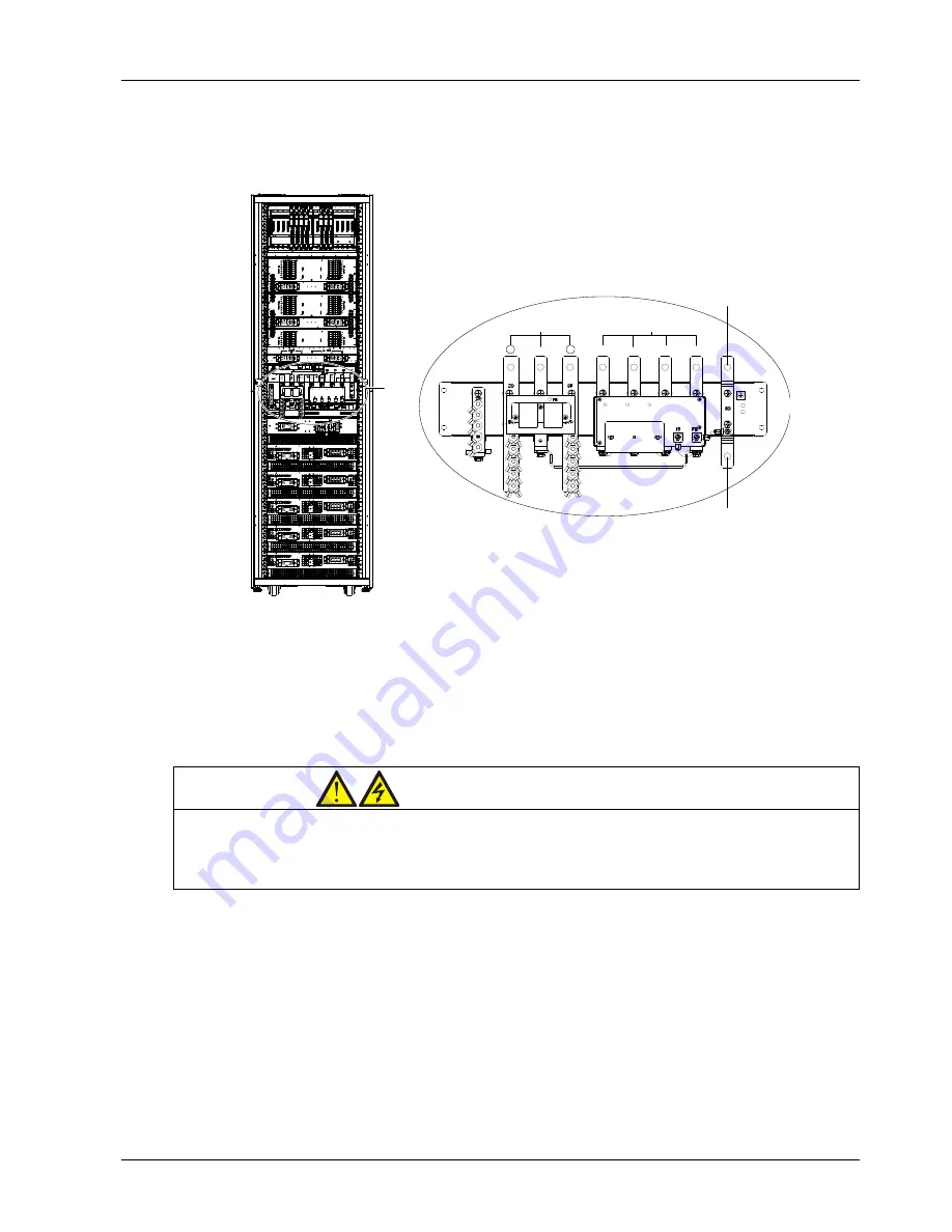
2. Open the back door of the UPS cabinet and remove the protective cover to gain access to the input
terminals, battery terminals and PE terminals, as shown in Figure 3-2.
A
+
N
-
U
V
W
N
Input terminal
Battery terminal
Input PE terminal
Output PE terminal
A amplified view
A
A Amplified view
Battery terminal
Input terminal
Input PE terminal
Output PE terminal
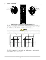
Figure 3-2
Input terminals, battery terminals and PE terminals (back view)
3. Connect the input PE cable to the input PE terminal. Note: The PE cable connection must be in accordance
with local and national codes of practice.
4. Connect the AC input cables to the input terminals (U-V-W-N) of the UPS and tighten the connections to
13Nm (M8 bolt). Ensure correct phase rotation.
5. Connect the battery cables between the battery terminals of the UPS and the BCB. Ensure correct battery
cable polarities.
Warning: hazardous battery terminal voltage 400Vdc
Ensure correct polarities of the connections from the terminals of the battery string to the BCB and from the BCB to the
battery terminals of the UPS, that is, positive to positive and negative to negative. Disconnect one or more battery cell
links between battery tiers. Do not reconnect these links or close the BCB without permission of the commissioning
engineer.
6. Connect the output cables.
1) If output distribution modules are configured, connect the L cables, N cables and PE cables between the
output terminals of the output distribution modules and the load according to Figure 3-3. Tighten the bolts
(M6) to 5Nm. Ensure correct phase rotation.


