30 Chapter 6 Parameter Description
EV3200 Door Control Inverter User Manual
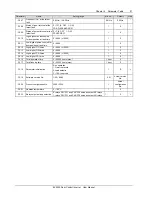
F4.01 Pulse number per
revolution
Setting range: 0 ~ 4000
【
100
】
F4.02 PG direction
Setting range: 0, 1
【
0
】
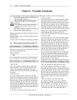
EV3200 inverter adopts vector control mode. Relevant
parameters of PG must be set if close loop vector control
mode is adopted.
In distance control mode, relevant parameters of PG should
also be set correctly so as to ensure the control effects.
EV3200 can only use two-phase PG.
Note
1. EV3200 asynchronous inverter can only use 24V open collector
or 24V push-pull PG.
2. EV3200 synchronous inverter can use 5V UVW incremental
PG.
3. For EV3200-2S0002A and EV3200-2S0004A, the default
setting of F4.01 is 100.
4 For EV3200-2S0002S and EV3200-2S0004S, the default setting
of F4.01 is 2500.
5. Function code F4.01 changes automatically with the change of
F6.00. When F6.00 is set to 0, F4.01 will change automatically to
200; when F6.00 is set to 1, F4.01 will change automatically to
2500.
F4.03 Magnetic pole initial
angle
Setting range: 0.0 ~ 359.9
【
0
】
When driving a synchronous motor, the magnetic pole nitial
angle of the motor will be obtained automatically after
tuning.
F4.04 Speed during door
width auto-learning
Setting range: 2.00 ~ 20.00Hz
【
5.00
】
Defines the operating frequency in door width auto-learning
process.
In order to reduce the door width error, this parameter must
not be too big so as to avoid the shock when the door is in
complete OD or CD status.
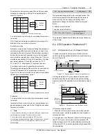
F4.05 Selection of door-width
auto-learning
Setting range: 0, 1
【
0
】
0: disabled
1: enabled
Set F4.05 to 1, press
(or when terminal auto-learning
command is valid), and the inverter will begin door-width
auto-learning automatically.
After the auto-learning, the setting of F4.05 will be restored
to 0 automatically.
Process of door-width auto-learning: After auto-learning is
started, the door will be closed, opened and then closed.
After the auto-learning is finished, the door width information
will be saved automatically.
Note
1. Relevant parameters of PG must be input correctly before the
auto-learning.
2. During auto-learning, there must not be any obstacles on the
slide rail of the door.
3. If you use the terminal to input the auto-learning command, you
should set F4.05 to 1 in advance as well.
4. If you use terminal to input the auto-learning command, you are
required to set F4.05 to 1 in advance.
5. Door width auto-learning function is valid in distance control
mode (F0.01=0).
6. The door width can be obtained manually when the inverter in
standby state. First, set F4.07 to 9999, close the elevator door
manually, and the inverter will display the CD complete pulse
value (P1); then pull the door open completely, and the inverter
will display the OD complete pulse value (P2). The high digits
and low digits of P1 and P2 can be displayed by setting the F9.01.
Refer to description of F9.01.
Calculate the door width (door width=|P2 - P1|), and input the
door width through F4.06 and F4.07.
F4.06 Low digits of pulse count
Setting range: 0 ~ 9999
【
0
】
The parameter saves the four low digits of pulse count
obtained by door width auto-learning (max: four digits).
F4.07 High digits of pulse count
Setting range: 0 ~
9999(× 10000)
【
0
】
The parameter saves the high digits of pulse count obtained
by door width auto-learning.
Door width= F4.07 × 10000+F4.06
The pulse number of door width obtained by auto-learning
can be changed via operation keypad.
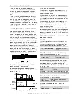
F4.08 Actual door width
Setting range: 0 ~ 9999mm
【
0mm
】
You may input the actual door width through F4.08, that is
complete CD is 0 and complete OD is the actual width set
by F4.08. When F4.08 is not 0, the door position is the
actual position in the unit of mm; when F4.08 is 0, the door
position is expressed by pulse number.
F4.09 PG cable broken detection
time for asynchronous motor
Setting range: 0.0 ~
10.0s
【
0s
】
When the PG input signal is detected abnormal, after the
time set by F4.09, the inverter will report PG cable broken
fault. If F4.09 is set to 0, PG cable broken detection function
is disabled.
F4.10 Ratio of gear
Setting range: 1.0 ~ 100.0
【
1.0
】
The ratio of shaft radius of traction wheel to motor shaft
radius, as shown in Figure 6-13.
Ratio of gear = shaft radius of traction wheel N1/motor shaft
radius N2.

