24 Chapter 6 Parameter Description
EV3200 Door Control Inverter User Manual
3. When the OD speed decrease signal is active, the
inverter decelerates within OD Dec time (F1.07) to OD
ending creep speed (F1.08), and operates at constant
ending speed in low-speed section when deceleration is
over.
4. When OD position limiting signal is active, the inverter
continues to run at OD low speed, and the inverter judges
the output torque. If the torque is bigger or equal to the
threshold of OD torque changing (F1.10), the inverter will
keep the OD torque of F1.11, ending the whole OD process.
5. When OD command is cancelled, the inverter will not
maintain the OD torque any more.
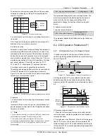
6.2.2 OD Operation Curve For Distance Control
Distance control is based on the self-learned door width
information. In the OD and CD processes, the pulse is
counted in real time, and compared with the preset pulse
value, so as to judge when to decrease the OD speed and
CD speed, and when the OD process and CD process
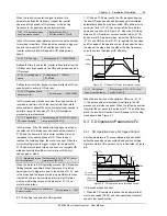
should be over. The control process is shown in Figure 6-5.
Three distance control modes are available, respectively
distance control 1, distance control 2 and distance control 3,
which have the same control logic and operation curve. In
distance control 1, the PG information is used both in
control and pulse counting, and under this condition, the PG
must be connected to the shaft of the motor. In distance
control 2 and distance control 3, the PG information is only
used in pulse counting, and under this condition, the PG
need not to be connected to the shaft of the motor.
Complete OD position
(
door width
)
OD
CD
Door width
F1.09
F1.06
F2.06
F2.09
Complete CD position (zero)
Figure 6-5 Illustration of distance control
The operation curve parameters in group F1 related to
distance control should be set correctly.
Door width auto-learning should be implemented before
distance control. The OD speed curve of distance control is
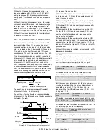
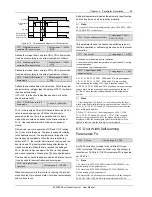
illustrated in Figure 6-6.
Frequency
F1.04
Time
F1.02
F1.08
F1.11
F1.10
F1.03
F1.07
OD
OD speed
decrease distance
OD position
limiting distance
ON
OFF
F1.06
×
door width
F1.09
Door width
0
0
Door width
OD start
creep distance
Door width
F1.01
×
door width
0
D1
D2
D3
Figure 6-6 OD operation curve for distance control
OD process of distance control:
1. When the OD command is active, the inverter starts at
start creep speed (F1.02), and then operates at constant
speed in low-speed section.
2. When reaching D1, the inverter starts to operate at OD
reference frequency (F1.04), and accelerates according to
OD Acc time (F1.03), and then operates at high speed after
the acceleration.
3. When reaching D2, the inverter decelerates within OD
Dec time (F1.07) to OD ending creep speed (F1.08), and
operates at constant ending speed in low-speed section
when after the deceleration.
4. When reaching D3, the inverter continues to run at OD
low speed in OD ending phase. If the output torque is bigger
or equal to the threshold of OD torque changing (F1.10), the
inverter will maintain the torque of F1.11, thus the whole OD
process is over.
5. When OD command is disabled, the inverter exits the OD
torque maintaining status.
Note
1. Acc time is the time taken for the inverter to accelerate from
0Hz (zero speed) to the maximum frequency (maximum speed).
2. Dec time is the time taken for the inverter to decelerate from
maximum frequency (maximum speed) to 0Hz (zero speed).
F1.00 OD start creep time for
speed control
Setting range: 10 ~ 9999ms
【
500
】
Defines the duration the inverter operates at start creep
speed in OD process under speed control.
F1.01 OD start creep distance
for distance control
Setting range: 0 ~ 30.0%
(door width)
【
15.0%
】
In OD process under distance control, the pulse number is
recorded in real time. When the pulse number is bigger or
equal to the product of F1.01 and the door width, the
inverter switches from OD start creep speed (F1.02) to OD
high speed (F1.04).
F1.02 OD start creep
speed
Setting range: 1.00 ~ 25.00Hz
【
7.00Hz
】
Defines the low operating frequency (speed) in OD process.
F1.03 OD Acc time
Setting range: 0.1s ~ 3600s
【
2.0s
】
Defines the time taken for the inverter to accelerate from the
OD start creep speed to the OD frequency.
F1.04 OD
reference frequency
Setting range: 0.00 ~ max frequency
【
20.00Hz
】
Defines the high operating frequency (speed) in OD
process.
F1.05 Rush hour
operation OD speed
Setting range: 0.00 ~ max
frequency
【
25.00Hz
】


