


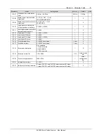


Chapter 4 Operation 13
EV3200 Door Control Inverter User Manual
4.1.4 Parameter Classification
The inverter has 141 function parameters, divided into 11
groups according to their functions:
1. F0 (F0.00-F0.08): basic operation function parameters
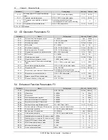
2. F1 (F1.00-F1.15): OD curve parameters
3. F2 (F2.00-F2.16): CD curve parameters
4. F3 (F3.00-F3.18): enhanced function parameters
5. F4 (F4.00-F4.12): door width auto-learning parameters
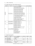
6. F5 (F5.00-F5.07): multi-function terminal parameters
7. F6 (F6.00 ~ F6.13): motor parameters
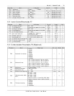
8. F7 (F7.00 ~ F7.10): vector control parameters
9. F8 (F8.00 ~ F8.10): communication parameters, reserved
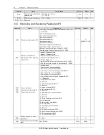
10. F9 (F9.00 ~ F9.22): display and monitoring parameters
11. FE: factory parameters, for factory use, not open to
users
4.1.5 Parameter Setting Method
The function parameters are set through the operation
keypad.
Look at the example below: modifying F1.04 (max CD
speed) from 20Hz to 30Hz.
1. Press the
key to enter programming state. The LED
on the keypad will display the F0 parameter group.
2. Press the
key to search the desired parameter group
(F1).
3. Press the
key to enter the corresponding function
parameter F1.00 in F1 parameter group.
4. Press the
key to enter the desired function parameter
F1.04.
5. Press the
key to display the function parameter value
(20.00, with the ones place “0” blinking).
6. Press the
key to shift to the digit to be modified, and
press the
or key to change the setting to 30.00.
7. Press the
key to save and display the next parameter
(F1.05).
8. Press the
key to exit to parameter group F1.
9. Press the
key to exit programming state (30.00
blinking).
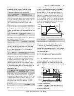
Figure 4-2 shows the application chart.
(
LED display
)
-F0-
-F1-
F1.00
F1.04
30.00
Exit after modification
Abandon the modification
2
0
.00
F1.05
▲
▲
-F1-
/
▲
1. Press PRG
to enter
programming
state and
display curent
parameter
group
2. Press
▲
to
search the
desired
parameter
group F1
3. Press FUNC/
DATA to enter the
corresponding
function parameter
F1.00 in F1
parameter group
4. Press
▲
to
enter the desired
function parameter
F1.04
5. Press FUNC/
DATA to display
the function
parameter value
6. Press
▲,
,
to change the
setting to 30.00
7. Press FUNC/
DATA to save
and display the
next parameter
F1.05
Continue to modify parameters
Return to previous display
Figure 4-2 Function parameter setting method
Note
Some parameters cannot be modified because they are detected
values or status parameters, e.g. F9.16, F9.17, and so on.
4.1.6 Display Of Parameters
1. Define the displayed parameters during operation or in
stopping state through F9.00 and F9.01.
2. During operation, the parameters defined by F9.00 can
be displayed one by one by pressing the
key on the
keypad.
3. In stopping status, the parameter defined by F9.00 can
be displayed one by one by pressing
key on the keypad.
4.2 Basic Applications
4.2.1 Motor Tuning
EV3200 series inverter uses vector control technique. It is
necessary to tune the motor parameters before operation.
Tuning can be started through the operation keypad. Before
tuning, motor must be free of load; otherwise, the results will
be inaccurate.
1. Tuning method in the case the load is asynchronous
motor.
Example where the inverter settings are factory settings:
1) Set general-purpose inverter keypad control mode: Set
F0.02 to 0.
2) Set PG type: Set F4.00 to 0 (24V incremental PG).