Chapter 6 Parameter Description 25
EV3200 Door Control Inverter User Manual
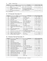
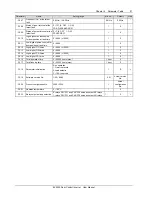
When the rush hour operation signal is active, this
parameter defines the frequency (speed) the inverter
operates at high speed in OD process, or the running
frequency in the general-purpose inverter mode.
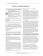
F1.06 OD speed decrease
point in distance control
Setting range: 60% ~
95%(door width)
【
70%
】
In the OD process under distance control, the pulse number
is recorded in real time. When the pulse number is bigger or
equal to the product of F1.06 and the door width, the
inverter will switch from OD speed to OD ending creep
speed.
F1.07 OD Dec time
Setting range: 0.1 ~ 3600s
【
2.0s
】
Defines the time taken for the inverter to decelerate from the
OD frequency (high speed) to the OD ending creep speed in
OD process.
F1.08 OD ending creep
speed
Setting range: 0 ~ 15.00Hz
【
3.00Hz
】
Defines the motor’s low frequency (speed) after the OD low
speed signal is active in OD process.
F1.09 OD position limit in
distance control
Setting range: 1 ~ 9999
【
600
】
In OD process under distance control, the pulse number is
recorded in real time. When the result of total door-width
pulse number subtracts the pulse number already passed is
smaller or equal to the value of F1.09, OD completion
processing is implemented.
F1.10 Threshold for
OD torque changing
Setting range: 0.0% ~ 100.0% (motor
rated torque)
【
50.0%
】
In OD process, if the OD position limiting signal is active or
the pulse count for distance control reaches the product of
F1.09 and the door width, the inverter continues to run at
low speed in the ending phase of OD. When the door
reaches the limited position, the motor is caught. When the
motor catching torque is bigger or equal to the product of
F1.10 and motor's rated torque, the door is in complete OD
status and maintaining the current torque until the door
opens again or stops.
F1.11 Maintaining torque
at OD completion
Setting range: 0.0% ~ 100.0% (motor
ratd torque)
【
50.0%
】
When the motor is in OD operating process, the OD position
limiting function is enabled. When the torque of catching
spinning motor is bigger or equal to the setting of F1.10, and
in the mean time the torque maintaining prohibition function
is disabled, the inverter maintains at complete OD status
with the maintaining torque of the product of F1.11 and
motor's rated torque.
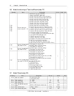
F1.12 OD operation curve selection in
distance control
Setting range: 0 ~ 1
【
0
】
0: F1.04 setting is observed in OD operation.
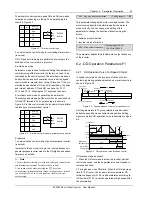
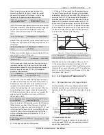
1: F1.04 and F1.06 are invalid, the OD process observes
the best OD speed and speed decrease point calculated
automatically based on the door width, OD optimum curve
correction factor (F1.13), Acc time and Dec time. As the
operation curve shows in Figure 6-7, when the OD creep
distance S1, OD optimum curve correction factor (F1.13)
and door width S are determined, adjust the OD Acc time
(F1.03) and OD Dec time (F1.07) to regulate the Acc slope
and Dec slope of the operation curve (the shorter the time,
the steeper the slope, and the higher the max frequency),
so as to achieve the highest OD efficiency.
Frequency
S1
S
Max. freq. 1
Max. freq. 2
Acc
Dec
F1.13
Door width
Figure 6-7 Optimum OD curve for distance control
F1.13 OD optimum
curve correction factor
Setting range: 3.0% ~ 15.0% (door
width)
【
10.0%
】
When the inverter runs at the optimum OD curve (F1.12 =
1), the pulse number is recorded in real time in the OD
process under distance control. When the left pulse number
is smaller than or equal to the product of F1.13 and the door
width, the inverter will switch from OD speed to OD ending
creep speed. See Figure 6-7.
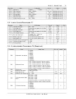
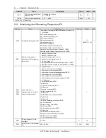
6.3 CD Operation Parameters F2
6.3.1 CD Operation Curve For Speed Control
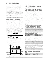
Set the parameters in F2 group related to speed control,
define the speed decrease contacts and position limiting
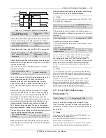
signal accurately. CD operation curve is illustrated in Figure
6-8.
Frequency
F2.04
Time
F2.02
F2.08
F2.00
F2.11
F2.10
F2.03
F2.07
CD
CD speed
decrease signal
CD position
limiting signal
ON
OFF
ON
OFF
ON
OFF
Figure 6-8 CD operation curve for speed control
CD process of speed control:
1. When the CD command is active, the inverter starts at
start creep speed (F2.02), and then operates at constant
speed in low-speed section.


