4.2
Field Setup Wizard
1.
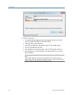
Use the Field Setup Wizard-Startup in Daniel MeterLink
™
and select the check boxes
that allow proper configuration for your meter (Temperature, Pressure, Meter
Corrections, Meter Outputs, Gas chromatograph setup, Continuous flow analysis
and View local display setup). Selections on this page will affect other configuration
selections.
a. Select Next to continue to General setup.
2.
Use General setup to configure the meter’s units system (U.S Customary or Metric
units) volume units, flow rate time, low flow cutoff, contract hour, enable reverse
flow alarm, set meter time and notepad comments.
a. Select Next to continue to Frequency/Digital Outputs page.
Note
The Meter’s Units system configured on the General Page affect the units for the optional
Local Display items.
3.
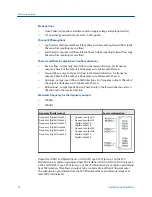
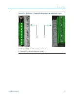
Set the Frequency/Digital Outputs Sources for either a frequency output or a digital
status.
a. Select the Source for each Frequency/Digital output and select the desired drive
Mode. The Mode options are Open Collector which requires an external
excitation voltage and pull-up resistor or TTL mode which outputs a 0-5 VDC
signal.
b. Select Next to continue to Frequency Outputs page.
Note
Frequency outputs 1 and Digital outputs 1 are paired together meaning the Digital outputs 1
will report the status for the parameter for Frequency outputs 1. Similarly, Frequency outputs
2 and Digital outputs 2 are paired together. Additionally, each Frequency output has an A and
B output phase.
4.
Configure Frequency output 1 and Frequency output 2 content, flow direction,
Channel B phase, maximum frequency output (Hertz) and full scale volumetric flow
rate.
a. Select Next to continue to Meter Digital Outputs.
5.
Select the Meter Digital Output parameters for Digital output 1A, Digital output 1B,
Digital output 2A and Digital output 2B based on Frequency validity or flow
direction.
If the output of the ultrasonic meter is reversed from what a flow computer is
expecting, select Inverted Operation. This changes the digital output from a HIGH
for a TRUE condition to output a LOW for a TRUE condition.
a. Select Next to continue to Analog Outputs.
6.
Configure Analog Outputs.
Configuration
88
Gas Ultrasonic Flow Meter
Summary of Contents for Daniel 3410 Series
Page 8: ......
Page 122: ...Engineering drawings 112 Gas Ultrasonic Flow Meter ...
Page 123: ......
Page 124: ......
Page 125: ......
Page 126: ......
Page 139: ...Open source licenses Installation manual 125 ...

