you hear a louder metallic noise at the stop (the cushioning
is reduced).
b)
Turn the hydraulic shock absorber (
25
) slightly back into the
stop sleeve (
27
) to extend the cushioning stroke. This once
again creates a soft stop.
The cycle time has now been optimized.
3.
Tighten the lock nut of the hydraulic shock absorber (
26
) to fix
the set position.
9
Maintenance and repair
Cleaning the mini slide
No special servicing is required for the mini slide. Note the
following if you would like to clean the device:
After cleaning, you must apply lubrication grease to the surface of
the piston rod and the ball bearings of the slide.
O
Apply the following types of grease to the piston rod or the
guide rail. During greasing, move the slide slowly in both
directions manually to achieve an even distribution of the
grease.
W
Piston rod:
– MICROLUBE GL 261
W
Guide rail/ball bearing
c)
Version
MG
:
– MICROLUBE GL 261
d)
Version
HG
:
– Stroke up to100 mm: Paralique P460
– Stroke from 125 mm: MICROLUBE GL 261
Maintaining the mini slide
Mini slides with elastic stops (versions EE, EM) are maintenance-
free.
O
Observe the system-specific maintenance intervals.
Lubricating the guide rail
It is recommended to grease the guide rail of the
MG
version mini
slides once a year (for the permissible grease see the section
“Cleaning the mini slide”).
Checking the seals
The seals of the mini slide may age faster under aggressive
ambient conditions. Defective seals will lead to pneumatic leaks.
1.
Check the seals regularly.
2.
Establish the maintenance intervals according to your ambient
conditions and enter them in the system-dependent
maintenance plan.
Exchanging the hydraulic shock absorbers
For mini slides with hydraulic cushioning, a maintenance interval
of 4-8 million cycles applies.
O
Replace hydraulic shock absorbers after 4-8 million cycles as
follows:
Shorter lubrication intervals are required in the case of:
W
High temperatures
W
Exposure to extensive dirt
W
Application near fat-dissolving liquids or vapors
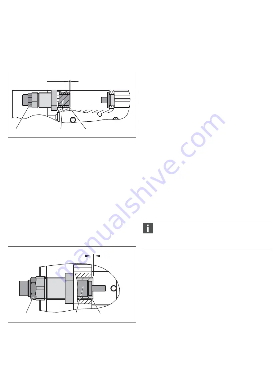
the position of the bolt (
22
) inside the sleeve (
21
).
E
1
must always be greater than 0 mm.
NOTICE!
The bolt (
22
) must not extend beyond the sleeve (
21
).
1.
Loosen the lock nut of the bolt (
24
).
2.
Set the position of the pneumatic cushioning to optimize the
cushioning effect. Proceed as follows:
a)
Begin with the full cushioning length (
E
1
=0 mm). For this
purpose, move the bolt (
22
) exactly to the edge of the sleeve
(
21
)
.
b)
Now reduce the cushioning length by turning the bolt (
22
) in
small steps back into the sleeve (
21
). Continue reducing the
cushioning length until you reach the lowest stop.
The cushioning effect has now been optimized.
3.
Tighten the lock nut of the bolt (
24
) to fix the set position.
Setting the cushioning length for hydraulic cushioning
O
Set the cushioning length by changing the position of the
hydraulic shock absorber (
25
) inside the stop sleeve (
27
).
E
2
must always be greater than 0 mm.
NOTICE!
The body of the hydraulic shock absorber (
25
) must
not extend beyond the stop sleeve (
27
).
1.
Loosen the lock nut (
26
) of the hydraulic shock absorber.
2.
Set the position of the hydraulic shock absorber (
25
) to
optimize the cycle time so that it is suitable for your
application. Proceed as follows:
a)
First reduce the cushioning stroke. Turn the hydraulic shock
absorber (
25
) step by step out of the stop sleeve (
27
) until
> 0
E
1
24
22
21
> 0
E
2
26
25
27
AVENTICS
| MSC |
R41209736–BAL–001–AF
| English
Setting the cushioning length
Setting the cushioning length for pneumatic cushioning
O
Set the cushioning length for the forward stroke by changing
27


