


38
07:30
06:00
OK
On
Off
06:00 - 07:30
20:00 - 21:30
0 6 12 18 24
0 6 12 18 24
0 6 12 18 24
0 6 12 18 24
0 6 12 18 24
0 6 12 18 24
0 6 12 18 24
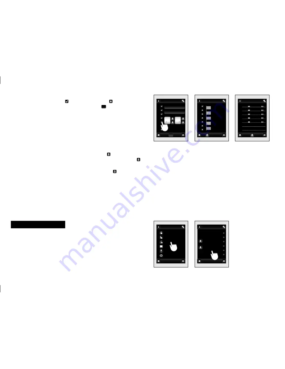
Dimming
menu is for all the lights where you want to control the
brightness (load R L, C - 250V).
Touch
Dimming
(fig. 149)
to display a selection of names you
created in menu
(fig. 150)
.
Note: Graphical representation of the contact / devices (Green -on, Red -off )
is for information only and may be infl uenced by the amount of information
processed or combining multiple control units RF Touch and RF Pilot.
By touching the Mo-Su icon it will activate the schedule on a given
day of the week
(fig. 146)
.
− active for the day, − disabled for
the day. To confi rm of selected schedule touch
OK
. If you want to set
additional schedule to continue with programming.
Note: For one day you can create up to 5 schedules a week and up to 5
schedules for Holiday mode. Times of programs may not overlap.
Daily
(fig. 147)
/
Weekly overview
(fig. 148)
shows the daily / weekly
overview of schedule.
To delete a time schedule in the
Daily overview
(
fig. 147)
indicate
the bar want to delete at then press the bin icon – to delete it. If
you do not select any of the programmed bars and press bin icon
you will remove all schedules in the day.
Weekly overview
(fig. 148)
− touch the bin icon to clear all
schedules.
Note: If
Holiday mode
is not enabled in
Settings
(see page 30) − it can not be
set here
(fig. 143)
. Component RFGA-1 has Weekly / Holiday mode.
Main menu / Dimming
fig. 149
fig. 150
fig. 147
fig. 148
fig. 146
hall light
hall light
hall light
Weekly overview
Daily overview
Mo
Tu
We
Th
Fr
Sa
Su
Tu
We
Th
Fr
Sa
Su
Mo
Main menu
Dimming
Temperature regulation
Quick control
Detectors
Blinds
Dimming
Switching
hall light
entrace light
room lamp 1
chandelier
hall lamp
room lamp 2
Mo
Tu
We
Th
Fr
Sa
Su


