


37
00:00
00:00
OK
0-10V
OK
100%
EN
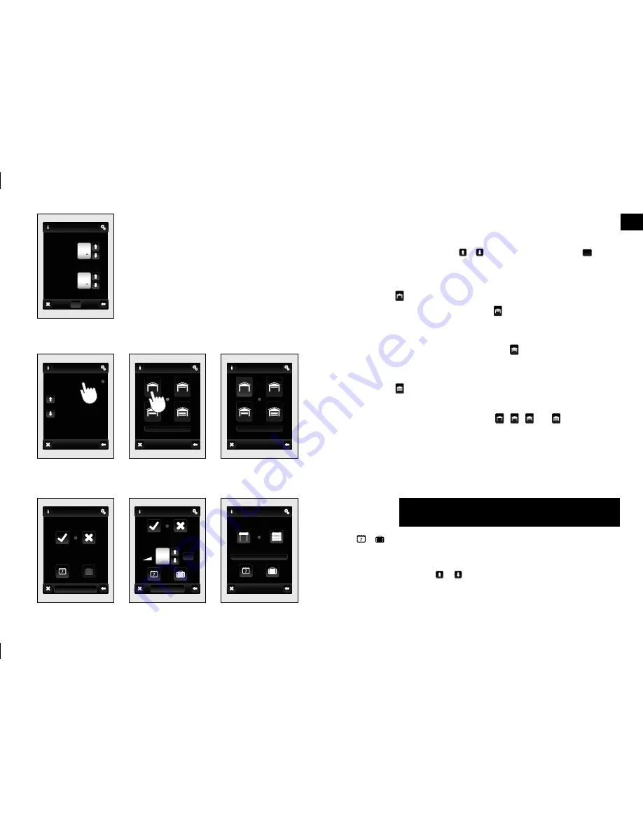
In the section
Setting time
all times for
Delay on
and
Delay off
. Time
delay can be set in the range from
2s to 60 minutes
. Touch-hour
time interval (or minutes) to
‹
indicate the information you want
then change
(fig. 139)
. Arrows / set time. Confi rm with
OK
.
RFGA-1 is displayed
(fig. 141)
:
•
Open
– touch
to open the garage door.
•
Intermediate position open
– touch
to open the garage door
to an partially opened position, which is set in the RFGA-1
component.
•
Intermediate position closed
– touch
to close the garage
door to an partially opened position, which is set in the RFGA-1
component.
•
Close
– touch
to close the garage door.
•
Stop
– press to stop the gate.
• After pressing the control buttons
,
,
or
will display
information about the direction of travel of the gate(s).
The position of the door is indicated by background colors
(fig. 142)
.
Main menu / Switching, Dimming, Blinds /
Weekly and Holiday mode
Touch
/
(Switching
fig. 143
, Dimming
fig. 144
*, Blinds
fig. 145
)
setup menu will appear.
Touch-hour time interval (or minutes) to
‹
mark information you
want to change. Arrows / will set the time of switch
On
and
switch
Off
.
* outside RFDA-73B-White, RF-RFGB-LED-550 and RF-White-LED-675
fig. 140
fig. 141
fig. 139
fig. 142
hall light
Switching
garage
garage
garage
Stop
Moving up
Stop
Delay
on
Delay
off
fig. 143
fig. 144
fig. 145
hall light
room lamp 1
window kitchen
Switch on
Switch off
Up
Down
Next functions
Next functions
Switch on
Switch off
Regulation
Setting


