54
Elcom, spoločnosť s ručením obmedzeným, Prešov
Elcom, spoločnosť s ručením obmedzeným, Prešov
55
Uniq 150
Service manual
Service
manual
Uniq 150
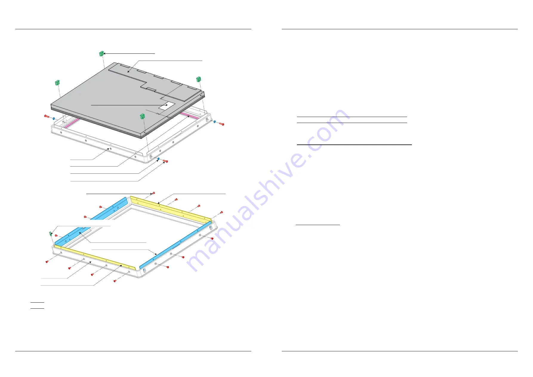
Figure 2.25.3. – Replacement of display with capacitive touch panel
33,5
96
Serrated lock washer M3 DIN6798
Screw M3 × 12 mm BN13255
LCD clip
Capacitive panel 15“ vandal proof
Tape TESA 4957 6 mm
Front cover
Insulation foil 25 × 12,5 × 0,25 mm
LED KM-2520VGC-A03 green
Screw M2,5 × 5 mm DIN965
Metal joining strip PP5000 TL
Front cover
Metal joining strip L PP5000 TL
Metal joining strip P PP5000 TL
Metal joining strip PP5000 TL
Note:
It is possible to use prepared maintanace sets of front panels Maintanace sets without display are primary used
for models with AUO display version, but they can by used for Turbo touch too.
In case of AUO verzion, there is neccesary to take out original display.
P280180000 Touchpanel resistive black frame-black multi TL without display
P2801800000 Touchpanel resistive white frame-white single TL without display
P2801800001 Touchpanel resistive gray frame-white single TL without display
P2801800002 Touchpanel resistive gray frame-black multi TL without display
Next sets are installed by display:
P2801800005 Touchpanel resistive black frame-black multi TL with display
P2801800006 Touchpanel resistive white frame-white single TL with display
P2801800007 Touchpanel resistive gray frame-white single TL with display
P2801800008 Touchpanel resistive gray frame-black multi TL with display
2.26. LED replacement and interconnection
2.26.1. Replacement and interconnection of lightguide
The lightguide consists only execution with AUO kit. The lightguide will be most likely demaged if the
lightguide is necessary to remove or is needed to replace some of the LED diodes.
It is necessary prepare before replacement:
–
tools for breaking removal of the lightguide and tools to clean lightguide remains the front cover
–
tin and soldering
–
Silicone OTTOSEAL black vandal – M990144
–
Power glue Loctite 401 – M250007
–
Tubing 2,4 mm – M010004
Process of replacement:
The lightguide is stick to the front cover with power glue and gaps between lightguide and cover are
filled with silicone because of IP protection.
1.
Truss and nick the lightguide with thin flat tool (shaver or screwdriver).
2.
Clean the cover of the remains of lightguide, silicone and glue.
3.
Glue diodes with cable on a new lightguide. There is a resistor 220R 0,6W on each of LED diode anode
to reduce the voltage.
4.
Put lightguide into front cover and spread a little of power glue on three protruding tabs from inner cover
side to fix lightguide in front cover.
5.
Fill gaps between lightguide and front cover edge from outher side with silicone.
Note: Installation of lightguide must be executed precisely according to figure. Note all the gaps are filled with
silicone, otherwise IP54 protection class cannot be guaranteed!
Summary of Contents for Uniq 150
Page 1: ...Uniq 150 Uniq 150 Service manual version 1 4 Elcom spolo nos s ru en m obmedzen m Pre ov...
Page 5: ...Elcom spolo nos s ru en m obmedzen m Pre ov 5 Service manual Uniq 150 1 General specification...
Page 7: ...Elcom spolo nos s ru en m obmedzen m Pre ov 7 Service manual Uniq 150 2 Structural part...


