32
3
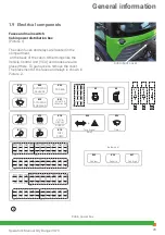
F5
40A
F2
60A
F4
70A
F1
40A
F3
100A
K2
K1
K3
K4
2
1
Operator’s Manual City Ranger 3070
Operator’s Manual City Ranger 3070
1.9 Electrical components -
continued
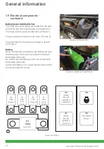
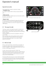
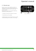
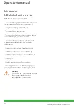
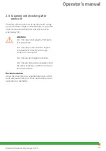
Battery power distribution box
The main fuses and relays are located on the rear
end of the machine in the battery compartment.
The main switch is also located here. (Picture 1)
To gain access remove the side cover. (Picture 2)
The placement of the fuses and relays is shown
in Picture 3.
Battery
When connecting or replacing the battery, be sure
that the power cords are connected correctly to
the battery terminals.
Be careful not to make any short circuit between
the battery terminals.
Clamp the battery so it is well fixed and put on the
terminal protection covers.
Battery compartment
Access to: Battery compartment
Fuses and relays
Group 1
Glow
Plugs
Group 2
ECU
Main
Group 3
MAIN
RELAY
GROUP 3
(VALVES)
MAIN
RELAY
GROUP 2
(LIGHTS)
ECU MAIN
RELAY
General information
Summary of Contents for City Ranger 3070
Page 1: ...Operator s manual Basic machine City Ranger 3070 ...
Page 4: ...Introduction ...
Page 6: ...General information ...
Page 39: ...Operator s manual ...
Page 50: ...Service and maintenance ...
Page 69: ...Conditions ...
Page 72: ...Wearing parts ...
Page 74: ...74 Operator s Manual City Ranger 3070 Notes ...

