30
Operator’s Manual City Ranger 3070
Operator’s Manual City Ranger 3070
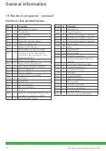
1.9 Electrical components - continued
Cabin fuses, relays and diode functions
Fuse
A
Function
F6
5
Main Relay ECU Coil
F7
10
Fuel Pump
F8
5
ECU Memory
F9
20
Starter
F17
10
Direction Indicator Relay
F18
1
Hazard Light Signal
F19
5
Relay VCU & Display
F20
5
Radio Memory & Cabin Light
F21
15
Steering Column (Key Switch,
Position Light, Low Beam, Horn,
Washer & Wiper)
F22
10
Stop Light Trailer
F23
1
Relay VCU & Display Coil
F24
30
VCU Output Supply 4 (Lights)
F25
10
A/C Compressor
F26
5
A/C Controller
F27
5
Antifrosting Thermostat
F28
20
Cabin fan
F29
15
Low Beam
F30
15
Work Light Left
F31
15
Work Light Right
F32
10
Wiper
F33
1
Sensor (Tachometer, Engine inlet
air filter & Trailer plug switch)
F34
5
ECU Cranking Signal
Fuse
A
Function
F35
5
Key Switch
F36
5
Fuel Pump Coil
F37
25
VCU Output Supply 1 (Valves)
F38
25
VCU Output Supply 2 (Valves)
F39
30
VCU Output Supply 3 (Valves)
F40
20
Mirror Heat
F41
20
Seat
F42
1
Seat Switch
F43
7,5 Radio & USB
F44
5
Monitor & Camera
F45
5
Armrest (Keypad & Direction
switch)
F46
15
TCU (Stop & Reverse light)
F47
15
A-frame Connector
F48
15
B-frame Connector
F49
15
Actuator
F50
15
Digital Out Rear
F51
5
Service Connector
F52
1
Turn Signals
F53
2
Position Light Left
F54
2
Position Light Right
F55
1
License Plate
F56
2
Position Light A & B-frame
General information
Summary of Contents for City Ranger 3070
Page 1: ...Operator s manual Basic machine City Ranger 3070 ...
Page 4: ...Introduction ...
Page 6: ...General information ...
Page 39: ...Operator s manual ...
Page 50: ...Service and maintenance ...
Page 69: ...Conditions ...
Page 72: ...Wearing parts ...
Page 74: ...74 Operator s Manual City Ranger 3070 Notes ...


