background image

T

ORQUE 

R

EFERENCES

 W

HEELS

79

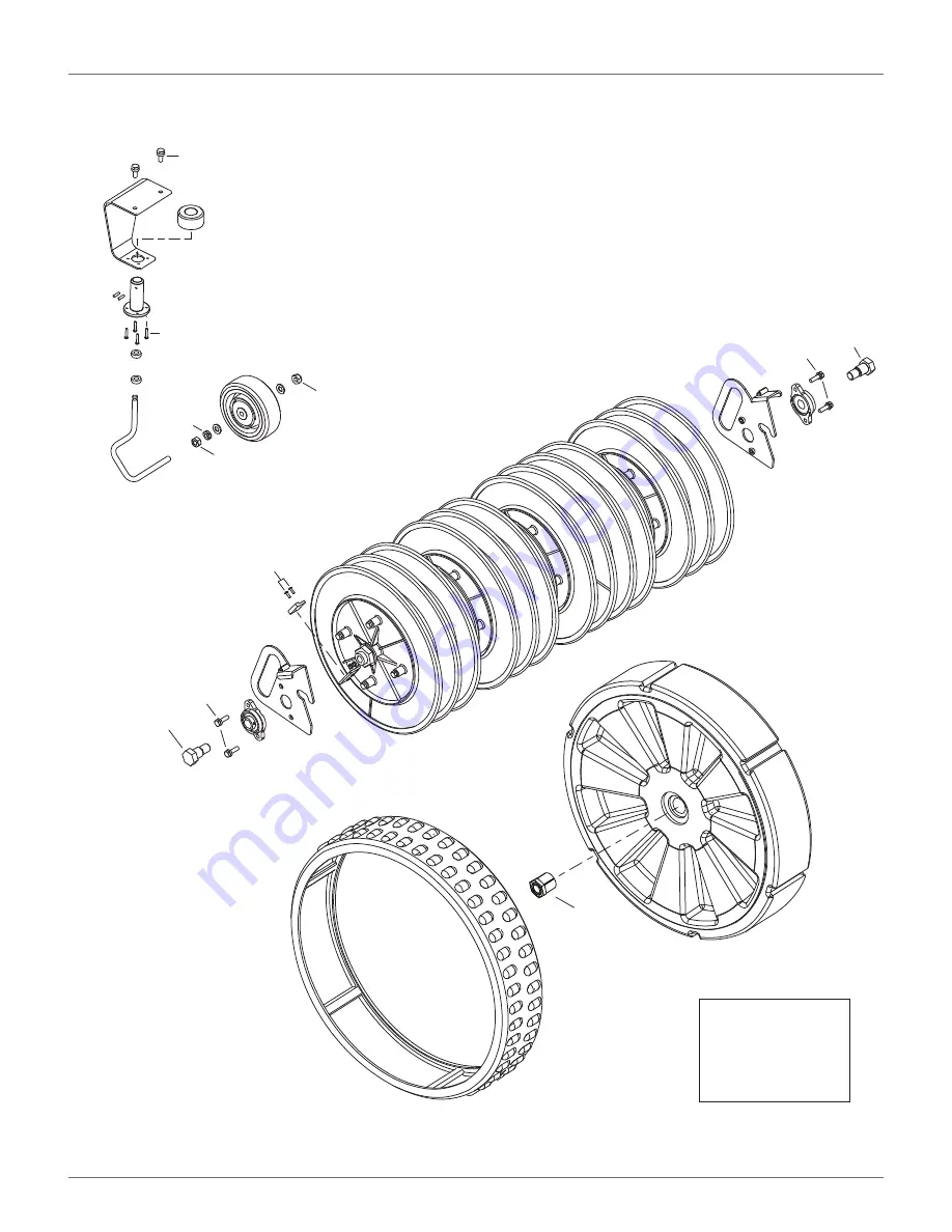
23.5 Wheels

7.5 lbf·

Ō

(10 N·m)

7.5 lbf·

Ō

(10 N·m)

7.5 lbf·

Ō

(10 N·m)

9 lbf·

Ō

(12 N·m)

Loctite 243

 Blue Threadlocker

††

Loctite 2701

  Green Threadlocker

0.75 - 1.0 lbf·

Ō

(1.0 - 1.5 N·m)

48 lbf·

Ō

(65 N·m)

9 lbf·

Ō

(12 N·m)

9 lbf·

Ō

(12 N·m)

1.5 lbf·

Ō

(2 N·m)

33 lbf·

Ō

(45 N·m)

33 lbf·

Ō

(45 N·m)

DRAFT 

08-06-2019 

Summary of Contents for RP-1200

Page 1: ...2019 ECHO Incorporated All Rights Reserved Technical Manual Range Picker RP 1200 EN ENGLISH P N 99922205439 VERSION 1 0 08 06 2019 www echorobotics com D R A F T 0 8 0 6 2 0 1 9...

Page 2: ...g Robots to Work On a Golf Course 12 Ball Collecting Robots 12 Ball Collecting Capacity 12 Working Areas 12 Chapter 7 Charging Station Requirements 13 Type of Charging Stations 13 Positioning of Charg...

Page 3: ...Advanced parameters 42 Chapter 11 Using the Robot 42 Safety Measures 42 Actions Menu 43 Service Menu 43 Service Menu 47 Chapter 12 Error Messages 51 Chapter 13 Connecting to Robots 51 Direct Interacti...

Page 4: ...ter 18 Notifications 65 To Add a New Notification 65 To Modify a Notification 65 To Delete a Notification 65 Chapter 19 Documentation 65 Chapter 20 Using the Application 66 Chapter 21 Robot Maintenanc...

Page 5: ...6 Chassis 77 Rear Sensors 78 Wheels 79 Wheel Gearbox 80 Barrow Components 81 Barrow Frame 82 Chapter 24 Technical Specifications 83 Battery 83 Weight and Dimensions 83 Software and Monitoring 83 Intel...

Page 6: ...when purchasing parts and assemblies www echorobotics com 1 3 FCC Declarations This equipment has been tested and found to comply with the limits or a Class A digital device pursuant to part 15 of the...

Page 7: ...t will stop move toward the peripheral wire then follow a trackborder back to the station loop wire When the robot detects the station loop wire it follows it to the charging station The station loop...

Page 8: ...r A pressure sensor which will cause the robot to change direction when it touches an obstacle 8 Rear wheel 9 Charge contact Connects to the charging arm on the charging station 10 Ball deflectors Pus...

Page 9: ...tbox ON 5 Navigation buttons Press to highlight menu options 6 Back button Press to exit a menu and return to previous level 7 Accept button Press to accept an operation or setting 8 Service menu butt...

Page 10: ...The rollover sensor detects if the robot has been tipped upside down or whether someone is trying to start the robot when it is upside down The temperature sensor measures the ambient outdoor temperat...

Page 11: ...tive State or the Service State 4 4 1 Operational States and Descriptions 1 Full basket detector 2 Ball counting band 3 Rotational speed detector 1 Enclosure top 2 Dust cover 3 Charging arm 4 Enclosur...

Page 12: ...ber or a certain time period has passed the robot will move towards the charging station connected to the drop pit in order to unload the balls The parameters for defining when the balls should be unl...

Page 13: ...has been issued If there is only one ball collecting robot operating it will return to the charging station with the drop pit If there are multiple robots working in the area it will return to its sp...

Page 14: ...leave the charging station and start collecting balls 4 4 3 Inactive Modes There are four inactive modes Alarm Mode Standby Mode Self Test Mode and OFF Mode Alarm Mode When the robot encounters a pro...

Page 15: ...ule for each field If the schedule dictates that a specific field must be worked at this time the robot will startworking in that field If there are no schedule constraints the robot will choose the f...

Page 16: ...to be collected Install a charging station and a station loop wire for each mowing robot used in the working area The station loop wire is required to enable the robot to return to its specific chargi...

Page 17: ...reas in which they will work Identify the number of balls hit per weekday and weekend day This can be estimated by considering the following Each driving range bay is used by 5 to 10 players per day d...

Page 18: ...t until the first robot has discharged all its balls and moved away The second robot will then dock with the charging station attached to the drop pit 7 1 Type of Charging Stations Single Zone This ch...

Page 19: ...it has collected If there is only one ball collecting robot only one charging station is required This charging station will trigger discharge of the balls and charge the robot s battery When the robo...

Page 20: ...ong Placing the drop pit charging station away from the driving range bays has advantages and disadvantages also Advantages Tracks made by the robot are out of sight Movements and noise is kept away f...

Page 21: ...ing station 9 3 Station Loop Wire Installation With Multiple Robots The following figure shows required dimensions Use this installation for a working robot to avoid hitting a robot at the charging st...

Page 22: ...stallation Wire 1 Field 1 is the station loop When in this field the robot will follow the wire to dock at the charging station Wire 2 Field 2 is a neighbor of Wire 1 Field 1 Wire 3 Field 3 is a neigh...

Page 23: ...ires for each field must be greater than or equal to 23 6 in 600 mm 9 6 1 Multi Field Overlaps An overlap is an area that lies within two fields It is used for the robot to transition from one field t...

Page 24: ...ge can be set to 0 9 7 Obstacles Obstacles are objects that the robot must avoid Exam ples are trees flower beds swing sets climbing frames trampolines sidewalks walking paths terraces ponds swimming...

Page 25: ...ome wet or flooded If meeting the minimum distance of 5 3 ft 1 6 m is not possible install a physical barrier around the water Install the charging station a minimum of 49 2 ft 15 m from the edge of t...

Page 26: ...n object place the approach and return sides of the peripheral wire directly next to each other do not cross or twist the wire secure with tie straps at 0 4 in 10 mm increments 9 9 Pseudo Islands Crea...

Page 27: ...and hold 9 on the numeric keypad until the TECHNICIANS SETTINGS menu appears 2 Select INFRASTRUCTURE then press Select Peripheral wires the press 3 On the WIRE SETTINGS screen select Wire CH X then p...

Page 28: ...loop the robot just needs to follow the wire when it is in this parcel 22 Select Neighboring parcels Select the D RANGE parcel and check the button ON 23 Press once to return to the PARCELS menu 24 S...

Page 29: ...op wire LOOP M Define whether the station is inside or outside the parcel s wire In the example above the station is outside the parcel s wire 9 12 2 Configuration Settings for the Ball Collecting Rob...

Page 30: ...e D RANGE parcel and check the button ON 10 Return to the PARCELS screen Select Edit parcels percentage Set the value to 100 for the D RANGE parcel 11 Return to the INFRASTRUCTURE screen and select St...

Page 31: ...the Charge parameter ON Set the Balls Unload parameter OFF Select Connected to parcels parameter and select the parcel in the loop wire LOOP BC2 13 Return to PAIRED STATIONS screen Create manual stat...

Page 32: ...utside the parcel s wire In the example above the station is outside the parcel s wire 9 12 8 Configuration for Mowing Robot 2 1 Press and hold 9 on the numeric keypad until the TECHNICIANS SETTINGS m...

Page 33: ...parameter OFF Set the Balls Unload parameter ON Select Busy loop and choose the required channel from those available CH4 in this example Select Connected to parcels param eter and select the parcel...

Page 34: ...e return direction required and check the Use trackborder parameter ON 8 Return to the PARCELS screen and select the parcel associated with the low density area wire CH1 in this example Rename the par...

Page 35: ...Return to the PARCELS screen and select the parcel associated with the low density area wire CH1 in this example Rename the parcel LD AREA in this example Define the return direction required and che...

Page 36: ...CHNICIANS SETTINGS menu appears 2 Select INFRASTRUCTURE then press Select Peripheral wires the press 3 Return to the WIRE SETTINGS screen Select Create new wire and set the Signal channel number to th...

Page 37: ...ate new wire and set the Signal channel number to the signal to be used for the return to station loop wire CH3 in this example 4 Return to the WIRE SETTINGS screen Select Create new wire and set the...

Page 38: ...arameter ON 9 Select Neighboring parcels Select the LD AREA parcel and check the button ON 10 Return to the PARCELS screen and select the parcel associated with the loop wire CH4 in this example Renam...

Page 39: ...the wire in terms of the associated channel is displayed In addition the current value and sign of the magnetic distance between the robot and the wire is indicated Signal channel The signal frequency...

Page 40: ...e trackborder This parameter defines whether the robot uses the trackborder when leaving or returning to the charging station NOTE This parameter value must be checked ON in all parcels which are not...

Page 41: ...d for a parcel Multiple start zones can be defined for the same wire parcel The Start Zone screen displays the following List of defined start zones For each start zone the line below it shows some ch...

Page 42: ...one containing the charging station the distances are measured from the entry point into the parcel shown in the figure below Angle Min Angle Max This is the angle that the robot will turn through to...

Page 43: ...nes which are the points at which the robot starts working after leaving the station Charge Defines whether the station is used to charge the robot or not Software version The current version of the s...

Page 44: ...demonstration mode Do not leave the robot unsupervised when it is operating in demonstration mode 10 6 Service The Service menu contains the following options Calibrations Information Tests Software u...

Page 45: ...be performed in the current sequence BUMPER SENSORS is the name of the current test Activate sensors The sides of the bumper that need to be tested by acti vating Bumper Left Bumper Right Disable Sens...

Page 46: ...ation that the coil connections are not good Drive Motor This checks the function of the drive motor It checks that the motor drives the wheel forward at 0 2 mph 0 1m s a current of 2 5 A is delivered...

Page 47: ...lect Update now then press The robot will contact the server download and then install the latest software version 10 7 Technician Settings Advanced parameters Max speed Sets the maximum speed at whic...

Page 48: ...ge stay Return to the charging station and stay there until it a new instruction is issued Mow Continue the working schedule after an interruption Go charge Return to the charging station charge the b...

Page 49: ...obot is to operate Mode selections are OFF The robot will not be connected to a network Client The robot will connect to the selected network as a client Access point The robot will use its inbuilt mo...

Page 50: ...ters Min temp Sets the lowest operating temperature for the robot The default value is 41 0 F 5 0 C Edit parcels percentage Use this option to view and modify each of the parcels that have been defin...

Page 51: ...This value should be positive when the robot is inside the peripheral wire loop If the distance is shown as a negative value it is necessary to reverse the phase See Infrastructure Peripheral wires W...

Page 52: ...d on Press to toggle the setting 8 Use to highlight Radius value then press 9 Use the numeric keypad to enter the required value 10 Press to return to the main menu 11 3 10 Advanced Parameters Press a...

Page 53: ...etworks This option appears when the robot is not connected or cannot detect a WiFi network SSID This displays the name of the WiFi network to which the robot is connected and allows you to modify it...

Page 54: ...oportion of times the robot will start working in the parcel To set the operating parameters 1 Press 2 Use the arrow keys to highlight Operations then press 3 Press or to highlight the required parame...

Page 55: ...address 11 4 7 System version To see the System version information Press Press the arrow keys to highlight Device then press Highlight System version then press Press or to scroll through the list V...

Page 56: ...and hold 0 on the numeric keypad until the ADVANCED PARAMETERS screen appears 12 Error Messages Refer to the Dealer Portal for a description of error messages 13 Connecting to Robots Communication wit...

Page 57: ...es Sports Field 1 Sports Field 2 Park West Park East The entity Park West has a child entity Golf Course Users and Roles A user has an account that is associated with an entity This is referred to as...

Page 58: ...l appear to show that the new entity has been created To see the new entity 1 Click on Management 2 Search for the Last name of the newly created entity and click on The newly created entity will appe...

Page 59: ...email into the address bar of a browser 3 Enter the password you wish to use There are no restrictions on the password Use a strong pass word that has at least 12 characters and which includes number...

Page 60: ...s and a mixture of upper and lower case letters 6 Click Register My Robots This page enables the user to search for a robot add a robot to the favorites list view the current status and issue a comman...

Page 61: ...imes when they occurred as well a map showing where the alarm occurred will be displayed To View a Map of a Robot s Movement 1 Click on the robot in the Favorites list 2 Click on the Map tab 3 Choose...

Page 62: ...e list is adapted Clicking on any entry will take you to that level To Create a New Entity 1 Select the parent of the new entity in the Entities list 2 Click on Create entity 3 Fill in all the details...

Page 63: ...can not be modified here This must be done by the user adapting his profile To Create a New User 1 Select the parent entity to which the user is to be added 2 Click Create user 3 Enter the details of...

Page 64: ...ccess the web server 1 Enter the URL https myrobot echoro botics com in the browser 2 Enter the email address used to activate the account 3 Enter the password defined when you activated the account 4...

Page 65: ...equired command 15 4 View the Robot History 1 Click on the robot in the Favorites list 2 Click on the History tab This page provides information on the activities and status of the selected robot over...

Page 66: ...the statistics are required 4 Click in the date field and choose the date required 5 Click Set 6 Click on 7 To change the presentation of the data click on to see cumulative data in a pie chart Click...

Page 67: ...4 Select the robot to be transferred 5 Click on Change Parent Entity 6 Search for the entity to which the robot is to be transferred 7 Click on the entity The robot will be transferred and the inform...

Page 68: ...ough to it you can follow the procedure below to gain access to your account 1 Go to https myrobot echorobotics com 2 Enter the email address used when the account was created 3 Enter the password def...

Page 69: ...The information given here refers to the opera tions available from the Management section of the web server 17 5 1 To View the Robots in an Entity 1 Enter the name or part of the name in the search...

Page 70: ...il will be sent to the new users email address from which the user can activate the account 17 6 4 To Delete a User 1 Click on the user in the list 2 Click X 3 Click 18 Notifications This section allo...

Page 71: ...robot s opera tion causing an accident and damaging parts NOTE If unusual operation or physical damage is noticed contact an authorized Authorized ECHO Robotics Dealer IMPORTANT Keep all nuts bolts a...

Page 72: ...en indicated with the GPS signal replace the Smartbox Service Tests indicate condition as appropriate Inspect the inside of the cover and the chassis cable condition check for cuts or abrasions attach...

Page 73: ...e Contacts Clean once per week 21 3 2 Sonar Sensors and Bumper Clean once per week Check that the bumper material is intact and not cut or torn If the bumper is damaged replace it 21 3 3 Chassis and C...

Page 74: ...ired Store the robot in a protected dry location where the temperature is above 32 F 0 C At the start of a new season 1 Move the power switch to the ON position 2 Place the robot onto the charging sta...

Page 75: ...er assembly to the cover 6 Assemble the bumper retaining screws tighten to 1 5 lbf ft 2 N m 7 Connect the bumper cable to the bumper 8 Complete the Bumper Service Test 22 3 Front Lift Cushion Replacem...

Page 76: ...ssemble the new wheel to the axle 3 Assemble the washer and nut Tighten the nut to 7 5 lbf ft 10 N m 22 6 Rear Wheel and Gear Motor Replacement Removal 1 Remove the cover 2 Loosen the wheel nut and re...

Page 77: ...43 Blue Threadlocker to the inte rior threads of the wheel nut Place the rear wheel assembly onto the gear motor output shaft tighten the nut to 48 lbf ft 65 N m 6 Complete the Drive Gear Motor Test 2...

Page 78: ...s mission and the message Lid not closed please select option again is displayed In order for the robot to be able to execute its missions the lid needs to be shut and to form a closed circuit between...

Page 79: ...bly contains two pairs of relays and the cabling between them When installing replacement magnets and relays visu ally examine the position to ensure correct alignment Run the service test to ensure t...

Page 80: ...dlocker Loctite 2701 Green Threadlocker 1 5 lbf 2 N m 1 lbf 0 7 N m 1 5 lbf 2 N m 1 5 lbf 2 N m 1 5 lbf 2 N m 6 lbf 5 N m 1 lbf 0 7 N m 1 5 lbf 2 N m 1 lbf 1 5 N m 1 5 lbf 2 N m 1 5 lbf 2 N m 5 lbf 7...

Page 81: ...ectrical Box Battery and Housing View A View A Loctite 243 Blue Threadlocker Loctite 2701 Green Threadlocker 2 lbf 3 N m 2 lbf 3 N m 1 5 lbf 2 N m 2 lbf 3 N m 4 5 lbf 6 N m 4 5 lbf 6 N m 2 lbf 3 N m 2...

Page 82: ...sis A A 7 Loctite 243 Blue Threadlocker Loctite 2701 Green Threadlocker 2 lbf 3 N m 2 lbf 3 N m 2 lbf 3 N m 2 lbf 3 N m 9 lbf 12 N m 2 lbf 3 N m 9 lbf 12 N m 4 5 lbf 6 N m 9 lbf 12 N m 4 5 lbf 6 N m 9...

Page 83: ...SENSORS 23 4 Rear Sensors 16 A A Loctite 243 Blue Threadlocker Loctite 2701 Green Threadlocker 0 75 1 lbf 1 0 1 5 N m 1 5 lbf 2 N m 1 5 lbf 2 N m 1 5 lbf 2 N m 9 lbf 12 N m 9 lbf 12 N m 9 lbf 12 N m...

Page 84: ...f 10 N m 7 5 lbf 10 N m 7 5 lbf 10 N m 9 lbf 12 N m Loctite 243 Blue Threadlocker Loctite 2701 Green Threadlocker 0 75 1 0 lbf 1 0 1 5 N m 48 lbf 65 N m 9 lbf 12 N m 9 lbf 12 N m 1 5 lbf 2 N m 33 lbf...

Page 85: ...80 TORQUE REFERENCES WHEEL GEARBOX 23 6 Wheel Gearbox 4 5 lbf 6 N m 2 lbf 3 N m Loctite 243 Blue Threadlocker Loctite 2701 Green Threadlocker 4 lbf 3 N m 1 lbf 1 5 N m D R A F T 0 8 0 6 2 0 1 9...

Page 86: ...nts Loctite 243 Blue Threadlocker Loctite 2701 Green Threadlocker 9 lbf 12 N m 9 lbf 12 N m 15 lbf 20 N m 15 lbf 20 N m 1 5 lbf 2 N m 1 5 lbf 2 N m 1 5 lbf 2 N m 3 lbf 4 N m 3 lbf 4 N m Hand assembly...

Page 87: ...e A A Loctite 243 Blue Threadlocker Loctite 2701 Green Threadlocker 9 lbf 12 N m 9 lbf 12 N m 9 lbf 12 N m 9 lbf 12 N m 9 lbf 12 N m 9 lbf 12 N m 9 lbf 12 N m 9 lbf 12 N m 9 lbf 12 N m 9 lbf 12 N m 9...

Page 88: ...and 140 F 20 C and 60 C Time to fully charge minimum 80 minutes Average mowing time per charge 110 minutes Average annual consumption 830 kWh Weight XXXXXX Length 46 4 in 1178 mm Width 53 0 1344 mm He...

Page 89: ...TECHNICAL SPECIFICATIONS DIMENSIONS 24 6 Dimensions 53 0 in 1344 mm 37 3 in 948 mm 44 6 in 1132 mm 13 4 in 341 mm 21 3 in 542 mm 46 4 in 1178 mm 23 7 in 603 mm 17 5 in 445 mm D R A F T 0 8 0 6 2 0 1...

Page 90: ...ECHO Incorporated 400 Oakwood Road Lake Zurich IL 60047 1 800 392 0329 www echorobotics com D R A F T 0 8 0 6 2 0 1 9...

Reviews: