W
IRE
I
NSTALLATION
P
ERIPHERAL
W
IRE
I
NSTALLATION
N
EXT TO
L
ANDSCAPING
17
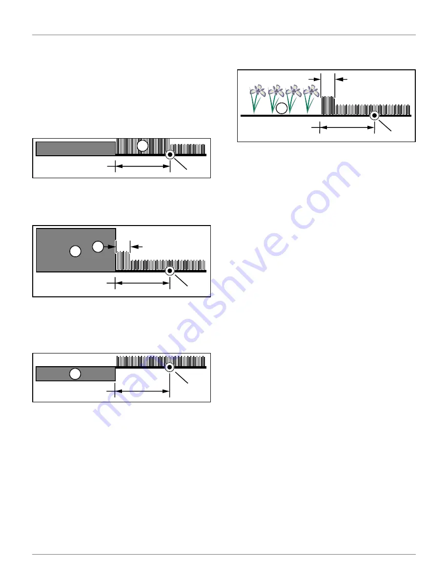
9.4 Peripheral Wire Installation
Next to Landscaping
NOTE
: The dimensional values shown apply when the
“Wire crossing distance” parameter is at the default
setting of 20 in. (510 mm).
9.4.1 Rough grass that does not need to be
mowed:
9.4.2 Raised hard landscaping:
9.4.3 Hard landscaping level with grass:
NOTE
: A path that crosses the field to be mowed should
be level with the grass.
9.4.4 Lawn-level planting (e.g. flower
bed).
9.5 Multiple Peripheral Wire
Installation
An installation may require multiple peripheral wires.
Each working area is defined by a peripheral wire that
starts and ends at a charging station. Each peripheral
wire contains a single parcel.
Each parcel must overlap with a neighboring parcel.
Each pair of wires or parcels which overlap must be
designated as neighboring parcels.
Multi-Field Installation
Wire 1 /Field 1 is the station loop. When in this field the
robot will follow the wire to dock at the charging
station.
Wire 2/Field 2 is a neighbor of Wire 1/Field 1. Wire
3/Field 3 is a neighbor of Wire 2/ Field 2.
The proportion of time that the robot spends working
in Fields 2 and 3 can determined by the percentage
values assigned to the corresponding fields through the
robot's working schedule. For Wire 1/Field 1 the
percentage can be set to 0.
The start and finish sides of the peripheral wire must lie
next to each other when they enter the charging
station. Install the start and finish sides of the periph-
eral wire for one field around the other field. The
distance between the peripheral wires for each field
must be greater than or equal to 23.6 in. (600 mm).
1 – Rough grass
2 – Peripheral wire
1 – Terrace / Path / Wall
2 – Peripheral wire
3 – Area not mowed
1 – Terrace / Path
2 – Peripheral wire
1
2
20 in.
(510 mm)
1
3
2
29.5 in.
(750 mm)
9.5 in.
(240 mm)
1
2
11.8 in.
(300 mm)
1 – Flower bed
2 – Peripheral wire
3 – Area not mowed
2
1
3
29.5 in.
(750 mm)
3.5 in.
(90 mm)
DRAFT
08-06-2019


