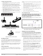
WIRING THE LED LUMINAIRE
1. Assembly sequence is common to both the MLLA2 and MLLA4 LED
luminaire products. The MLLA2 luminaire is used in the supporting
illustrations.
2. To gain access to the luminaire input wiring connections loosen the eight
(8) #10-32 x .75” stainless steel cover screws (see Figure 9) until screws
are free from driver housing. Screws are a captive type and should not be
fully removed from the light engine fitting assembly.
3. Pull the retention clips on the light engine assembly to free it from the
driver housing and pivot the light engine fitting on the driver housing
service hooks (see Figure 10). This shall expose the internal volume of the
driver housing and the input wiring terminal carriers.
4. Connections to the LED light engine and LED driver are pre-wired and
do not require any further processing. Route the Line, Neutral and
Ground input wires to the wire terminal carrier (see Figure 11) and make
connections per system wiring diagrams (see Figures 14A, 14B and
14C) using methods that comply with all applicable codes. Terminate the
equipment grounding connector (green) first, the common (white) next,
and finally, the line voltage (black). Ensure all electrical connections have
been completed and terminal block lever locks are fully seated and secure.
Note- standard entries in driver housing and 3/4” NPT thread.
5. Connect module battery connections (white wires) as the battery is
shipped disconnected to prevent discharging.
6. Connect Emergency Backup Module converter connection (Red wires) as
the last electrical connection. This connection enables electrical function in
the backup module and failure to make this connection will result in non-
function of the luminaire.
7. To connect remote test switch (customer supplied) locate the brown and
purple leads from the emergency backup driver and connect remote test
switch wires using 3-pole wire terminals provided (see wiring diagram).
8. If using the dimming function of the LED driver, use only wires rated to
600V minimum. Dimming circuit operates on 0-10 VDC; dimmer shall be
suitably certified for the intended installation environment (e.g. Hazardous,
Ordinary Locations, etc...).
9. Re-install the light engine fitting and tighten all eight (8) cover mounting
screws 23 in.-lbs. (2.6 N-m) using the bolting sequence directed in Figure
9. Verify that no luminaire wiring is pinched or trapped between light
engine and driver housing. Start all screws prior to tightening.
10. Replace any damaged or missing cover screws. Consult factory for
replacement parts.
WIRING INSTALLATION CHECKLIST
1. Verify sufficient quantity of Eaton’s STL thread lubricant is on conduit
entries and that all unused conduit entries on the end caps are closed
with lubricated plugs (see Figure 13).
2. Verify conduit is installed to at least five (5) full threads into the end cap
conduit entries. Recommend approximately 1/8” bead quantity of Eaton’s
STL thread lubricant on conduit entries.
3. Verify installed conduit is torqued to 42-52 ft.-lbs. (57-71 N-m) for 3/4”
plug.
4. Verify supply wires are connected to luminaire wire leads per Figure 14A,
Figure 14B or Figure 14C.
5. Verify all electrical connections are properly made and secure.
6. Verify all wires are routed correctly and are fully contained in the driver
housing without any wires being pinched when the light engine fitting
is rotated back into position. Re-attach driver cover to luminaire driver
housing using the bolt tightening sequence in Figure 9.
7. Verify captive attachment screws are tightened to 23 in.-lbs. (2.6 N-m) and
light engine fitting is in flush contact with driver housing.
IF 1946 • 09/22
Copyright © 2022, Eaton’s Crouse-Hinds Division Page 5
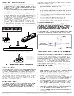
Figure 13. NPT Fitting
Figure 9. Driver Housing Screw Locations
Figure 10. Light Engine Rotated for Servicing
Figure 11. Input Wiring Terminal Carrier
Figure 12. Driver Housing Safety Cable Mounting Locations
NOTE
A maximum of 8 luminaires may be daisy chained on a single circuit. See
luminaire wiring diagrams.
THIRD ANGLE PROJECTION
CCHSY-SW-Template-D
SW_REV 11/2015
DO NOT SCALE DRAWING
NOTES:
1.
A
B
C
D
1
2
3
4
5
6
7
8
A
D
C
B
8
7
6
5
4
3
2
1
Your name
ASSY2
CAT2
CAT1
ASSY1
ARE IN
MILLIMETERS.
DIMENSIONS IN [ ] ARE IN
ALL PRIMARY DIMENSIONS
UNLESS OTHERWISE SPECIFIED,
MM/DD/YYYY
Your Name
WITH ASME Y14.5 2009.
DIM AND TOL IN ACCORDANCE
±
±
±
±
.1
.3
INCHES.
rev
0000000
WT. 15.85 LB
SCALE 2:3
FIRST MADE FOR Catalog Family
Title Line 1
APPROVED BY
DRAWN BY
Finish
... THICK
Material
mm
in.
.13
.000
1.5
Your Name
THIS IS PROPERTY OF EATON AND CONTAINS CONFIDENTIAL AND
TRADE SECRET INFORMATION. POSSESSION DOES NOT CONVEY
ANY RIGHTS TO LOAN, SELL OR DISCLOSE SAID INFORMATION.
REPRODUCTION OR USE FOR ANY PURPOSE OTHER THAN WHICH
IT WAS SUPPLIED MAY NOT BE MADE WITHOUT EXPRESS
WRITTEN PERMISSION OF EATON. THIS DRAWING IS ON LOAN
AND IS TO BE RETURNED UPON REQUEST.
Title Line 2
Your Name
MM/DD/YYYY
1.5
±
.005
±
.01
±
±
ANGLES
.XXX
.XX
.X
REDRAWN DATE
ORIGINAL DATE
UNLESS OTHERWISE SPECIFIED
TOLERANCES
MATERIAL:
FINISH:
APPROVED BY
CHECKED BY
USED ON
APPLICATION
NEXT ASSY.
TITLE
CODE IDENT. NO.
SIZE
REV.
D
SHEET 6 OF 6
CODE ...
5
6
7
8
2
4
3
1
THIRD ANGLE PROJECTION
CCHSY-SW-Template-D
SW_REV 11/2015
DO NOT SCALE DRAWING
NOTES:
1.
A
B
C
D
1
2
3
4
5
6
7
8
A
D
C
B
8
7
6
5
4
3
2
1
Your name
ASSY2
CAT2
CAT1
ASSY1
ARE IN
MILLIMETERS.
DIMENSIONS IN [ ] ARE IN
ALL PRIMARY DIMENSIONS
UNLESS OTHERWISE SPECIFIED,
MM/DD/YYYY
Your Name
WITH ASME Y14.5 2009.
DIM AND TOL IN ACCORDANCE
±
±
±
±
.1
.3
INCHES.
rev
0000000
WT. 15.85 LB
SCALE 2:3
FIRST MADE FOR Catalog Family
Title Line 1
APPROVED BY
DRAWN BY
Finish
... THICK
Material
mm
in.
.13
.000
1.5
Your Name
THIS IS PROPERTY OF EATON AND CONTAINS CONFIDENTIAL AND
TRADE SECRET INFORMATION. POSSESSION DOES NOT CONVEY
ANY RIGHTS TO LOAN, SELL OR DISCLOSE SAID INFORMATION.
REPRODUCTION OR USE FOR ANY PURPOSE OTHER THAN WHICH
IT WAS SUPPLIED MAY NOT BE MADE WITHOUT EXPRESS
WRITTEN PERMISSION OF EATON. THIS DRAWING IS ON LOAN
AND IS TO BE RETURNED UPON REQUEST.
Title Line 2
Your Name
MM/DD/YYYY
1.5
±
.005
±
.01
±
±
ANGLES
.XXX
.XX
.X
REDRAWN DATE
ORIGINAL DATE
UNLESS OTHERWISE SPECIFIED
TOLERANCES
MATERIAL:
FINISH:
APPROVED BY
CHECKED BY
USED ON
APPLICATION
NEXT ASSY.
TITLE
CODE IDENT. NO.
SIZE
REV.
D
SHEET 6 OF 6
CODE ...
THIRD ANGLE PROJECTION
CCHSY-SW-Template-D
SW_REV 11/2015
DO NOT SCALE DRAWING
NOTES:
1.
A
B
C
D
1
2
3
4
5
6
7
8
A
D
C
B
8
7
6
5
4
3
2
1
Your name
ASSY2
CAT2
CAT1
ASSY1
ARE IN
MILLIMETERS.
DIMENSIONS IN [ ] ARE IN
ALL PRIMARY DIMENSIONS
UNLESS OTHERWISE SPECIFIED,
MM/DD/YYYY
Your Name
WITH ASME Y14.5 2009.
DIM AND TOL IN ACCORDANCE
±
±
±
±
.1
.3
INCHES.
rev
0000000
WT. 15.59 LB
SCALE 1:1
FIRST MADE FOR Catalog Family
Title Line 1
APPROVED BY
DRAWN BY
Finish
... THICK
Material
mm
in.
.13
.000
1.5
Your Name
THIS IS PROPERTY OF EATON AND CONTAINS CONFIDENTIAL AND
TRADE SECRET INFORMATION. POSSESSION DOES NOT CONVEY
ANY RIGHTS TO LOAN, SELL OR DISCLOSE SAID INFORMATION.
REPRODUCTION OR USE FOR ANY PURPOSE OTHER THAN WHICH
IT WAS SUPPLIED MAY NOT BE MADE WITHOUT EXPRESS
WRITTEN PERMISSION OF EATON. THIS DRAWING IS ON LOAN
AND IS TO BE RETURNED UPON REQUEST.
Title Line 2
Your Name
MM/DD/YYYY
1.5
±
.005
±
.01
±
±
ANGLES
.XXX
.XX
.X
REDRAWN DATE
ORIGINAL DATE
UNLESS OTHERWISE SPECIFIED
TOLERANCES
MATERIAL:
FINISH:
APPROVED BY
CHECKED BY
USED ON
APPLICATION
NEXT ASSY.
TITLE
CODE IDENT. NO.
SIZE
REV.
D
SHEET 7 OF 7
CODE ...

