72
9.2.1. ARC-EM/2.0
The master unit is designed for fl ush mounting. Spacing adapters for reducing the installation
depth are available on request.
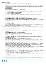
Figure: Mounting the master unit ARC-EM/2.0
Wiring of the master unit, overview
The master unit can be connected to the following:
•
secondary circuits of the current transformers of the switchgear
•
the trip circuits of the circuit breakers
•
alarm
circuits
•
auxiliary supply circuits
•
protective
earthing
•
connections to I/O units (data communication and auxiliary supply)
•
connections to other master units or arc quenching device
NOTE! The auxiliary supply connection is different to ARC-EM In ARC-EM/2.0 the auxiliary supply is
connected to terminals X3:17 and X3:18.
Wiring secondary circuits of the current transformers
Connect the secondary circuits of the current transformers to the following screw connectors
in the back plate:
•
X1-1, X1-2 (L1)
•
X1-3, X1-4 (L2/I0)
•
X1-5, X1-6 (L3)
The arc protection system can also be single or two-phase connected. Three-phase connec-
tion is nevertheless recommended for optimal operating speed.
NOTE! The current measuring channels L1 and L3 must be used in connection with two-phase cur-
rent measuring. If only two phases are connected, they should be connected to L1 and L3.
Single-phase current or earth-fault current must always be connected to the current measu-
ring channel L2/I0.
NOTE! The specifi ed operating time of 7ms can only be guaranteed for three-phase current measu-
rement.
Summary of Contents for ARCON 2.0 Series
Page 51: ...51 7 6 Block diagram 7 6 1 ARC EM 2 0 Figure Connections of ARC EM 2 0...
Page 54: ...54 7 6 4 ARC EL3 2 0 7 6 5 ARC EC1 2 0...
Page 64: ...64 9 Construction 9 1 Dimensional drawings 9 1 1 ARC EM 2 0 panel and semi flush mounting...
Page 65: ...65 9 1 2 ARC EP10 2 2 0 din rail mounting...
Page 66: ...9 1 3 ARC EP10 2 0 din rail mounting 66...
Page 67: ...67 9 1 4 ARC EL3 2 0 din rail mounting...
Page 68: ...68 9 1 5 ARC EC1 2 0 din rail mounting...
Page 69: ...69 9 1 6 Fiber sensor mounting r min 50 mm...
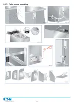
Page 70: ...70 9 1 7 Point sensor mounting...
Page 82: ...82 10 Application examples 10 1 Applications 10 1 1 With a main busbar system...
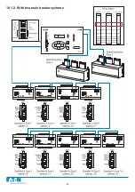
Page 83: ...83 10 1 2 With two main busbar systems...
Page 84: ...84 10 1 3 With two main busbar systems and additional zone selection 4 zones...
Page 85: ...85...

