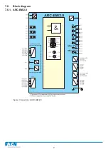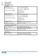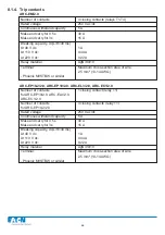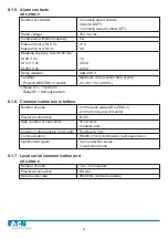
7.1.4. ARC-EC1/2.0
X1-1,3:
Current input IL1
X1-5,7:
Current input IL2 / Io
X1-9,11.
Current input IL3
X2-1:
+24V supply from master
unit or external power
supply
X2-2:
GND
X2-3:
CAN-L Zone
=
COM1,
COM2
X2-4:
CAN-H information
(L>,
I>)
X2-5:
Serial
B
master
slave
X2-6:
Serial
A
com
X2-7:
DI
GND
L>
X2-8:
DI
(24-48Vdc)
X2-9:
DO
GND
TRIP
X2-10:
DO
+24Vdc
X2-11:
X2-12:
X2-13:
X2-14:
X2-15:
Trip relay (NO)
X2-16:
Trip relay (NO)
Figure: ARC-EC1/2.0 interfaces
48
ARC-EC1/2.0
ARCON
®
Summary of Contents for ARCON 2.0 Series
Page 51: ...51 7 6 Block diagram 7 6 1 ARC EM 2 0 Figure Connections of ARC EM 2 0...
Page 54: ...54 7 6 4 ARC EL3 2 0 7 6 5 ARC EC1 2 0...
Page 64: ...64 9 Construction 9 1 Dimensional drawings 9 1 1 ARC EM 2 0 panel and semi flush mounting...
Page 65: ...65 9 1 2 ARC EP10 2 2 0 din rail mounting...
Page 66: ...9 1 3 ARC EP10 2 0 din rail mounting 66...
Page 67: ...67 9 1 4 ARC EL3 2 0 din rail mounting...
Page 68: ...68 9 1 5 ARC EC1 2 0 din rail mounting...
Page 69: ...69 9 1 6 Fiber sensor mounting r min 50 mm...
Page 70: ...70 9 1 7 Point sensor mounting...
Page 82: ...82 10 Application examples 10 1 Applications 10 1 1 With a main busbar system...
Page 83: ...83 10 1 2 With two main busbar systems...
Page 84: ...84 10 1 3 With two main busbar systems and additional zone selection 4 zones...
Page 85: ...85...


