22
3.1.2. Overcurrent alarm
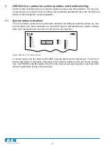
Figure: ARCON 2.0 activated due to overcurrent
Figure: ARC-EC1/2.0 indicates overcurrent on channel L2
When any component of the current measuring system detects a current exceeding the setting
value of the unit, it sends current information to all other units. The I>int indicator light is lit when
the master unit measures the overcurrent. If the current information is obtained from outside the
master unit (either through the BI/O bus or from a current I/O unit), the I>ext LED indicator light
is lit. The indicator light of the activated stage is lit in the current I/O unit (ARC-EC1/2.0).
Figure: Reading measured currents in the CURRENT mode
ARC-EM/2.0
L1/L3 L2/Io
0.1
L1
L2
L3
CURRENT TRANSFORMER
X1
0.5
0.1
CURRENT
USE THE TRIMMER FOR SET THE LEVEL
OF PICK-UP CURRENT L1/L3
CURRENT IN PHASE 1
CURRENT IN PHASE 2
CURRENT IN PHASE 3
USE THE TRIMMER FOR SET THE LEVEL
OF PICK-UP CURRENT Io/L2
Summary of Contents for ARCON 2.0 Series
Page 51: ...51 7 6 Block diagram 7 6 1 ARC EM 2 0 Figure Connections of ARC EM 2 0...
Page 54: ...54 7 6 4 ARC EL3 2 0 7 6 5 ARC EC1 2 0...
Page 64: ...64 9 Construction 9 1 Dimensional drawings 9 1 1 ARC EM 2 0 panel and semi flush mounting...
Page 65: ...65 9 1 2 ARC EP10 2 2 0 din rail mounting...
Page 66: ...9 1 3 ARC EP10 2 0 din rail mounting 66...
Page 67: ...67 9 1 4 ARC EL3 2 0 din rail mounting...
Page 68: ...68 9 1 5 ARC EC1 2 0 din rail mounting...
Page 69: ...69 9 1 6 Fiber sensor mounting r min 50 mm...
Page 70: ...70 9 1 7 Point sensor mounting...
Page 82: ...82 10 Application examples 10 1 Applications 10 1 1 With a main busbar system...
Page 83: ...83 10 1 2 With two main busbar systems...
Page 84: ...84 10 1 3 With two main busbar systems and additional zone selection 4 zones...
Page 85: ...85...


