


19
2.2.4. ARC-EC1/2.0
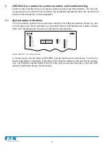
Figure: Current I/O unit ARC-EC1/2.0 front panel
1. Programming switches (factory setting - DIP switches 1...5 in „ON“ position / 6...8
in „OFF“ position
NOTE! The confi guration of the DIP switches must be done properly before operating the system!
2. POWER indicator light, indicates the supply voltages of each component are in order.
3. COM indicator light, lit when the master units and I/O units are communicating.
4. ERROR indicator light, indicates an internal fault detected by the component’s self-
diagnostics. Such faults include faulty current transformer or phase current unbalance.
5. Connector sockets for the modular cables
6. LED lights indicating that I> stage has started
7. Terminals for three current transformers
8. Current transformer programming switches (factory setting - all DIP switches in „ON“
position
NOTE! The confi guration of the DIP switches must be done properly before operating the system!
9. Overcurrent setting knob (IL1, IL3), setting range 0.5...6*In (factory setting 2.0*In)
10. Overcurrent setting knob (IL2, I0), setting range 0.05...5*In (factory setting 2.0*In)
NOTE! The confi guration of the overcurrent setting must be done properly before operating
the system!
11. I/O unit trip relay activated
12. Terminal block for external communication and BI/O channels and trip signal
13. Indicator LEDs for current setting
Summary of Contents for ARCON 2.0 Series
Page 51: ...51 7 6 Block diagram 7 6 1 ARC EM 2 0 Figure Connections of ARC EM 2 0...
Page 54: ...54 7 6 4 ARC EL3 2 0 7 6 5 ARC EC1 2 0...
Page 64: ...64 9 Construction 9 1 Dimensional drawings 9 1 1 ARC EM 2 0 panel and semi flush mounting...
Page 65: ...65 9 1 2 ARC EP10 2 2 0 din rail mounting...
Page 66: ...9 1 3 ARC EP10 2 0 din rail mounting 66...
Page 67: ...67 9 1 4 ARC EL3 2 0 din rail mounting...
Page 68: ...68 9 1 5 ARC EC1 2 0 din rail mounting...
Page 69: ...69 9 1 6 Fiber sensor mounting r min 50 mm...
Page 70: ...70 9 1 7 Point sensor mounting...
Page 82: ...82 10 Application examples 10 1 Applications 10 1 1 With a main busbar system...
Page 83: ...83 10 1 2 With two main busbar systems...
Page 84: ...84 10 1 3 With two main busbar systems and additional zone selection 4 zones...
Page 85: ...85...