
36
4. System
commissioning
The following equipment is required for commission testing:
Current supply for feeding either primary or secondary current.
A
fl ashlight or other source of bright light
A multi-function measuring instrument including a clip-on ammeter and resistance measure-
ment for verifying the operation of potential-free output contact.
The
fl ashlight must be able to provide a suffi ciently long light pulse for the sensors.
If you are using a torch, adjust the beam until its edge is sharp to ensure sensor activation.
Commissioning testing must be documented in writing, detailing system operation and set-
tings.
4.1.
Testing - general
Before initiating the testing, determine the system confi guration and scope. Pay particular
attention to safety during the work
and ensure the testing will not cause unnecessary trip-
ping of feeders that are in use.
Determine the following:
Is any unit connected to another master unit or protection relay via a BI/O bus?
Where have the trips been wired to from the master units and I/O units?
What is the total number of I/O units and sensors? Has the system been confi gured as in-
structed? (see section 3.4)
Has any other protection or measuring equipment been connected to the current measuring
circuits?
Have any sensors been placed near live components?
4.2.
Performing the testing
The system should be tested systematically, since correct operation of the arc protection sy-
stem guarantees personal safety.
Activate each sensor separately and ensure at the master unit that the light information tra-
vels through the entire communication channel.
Once you have tested each sensor channel separately, activate a few sensor channels’ to-
gether with current criteria and verify tripping (preferably at least one trip per I/O unit). Enter
the activated channels under items 5 and 6 and the trip in column 7 in Table 4.2-1.
If light or current identifi er information is transferred from one master unit to another through
the BI/O bus, ensure that this information is transferred between the master units. Enter the
light or current information ( L > or I > ) received by the master unit under item 2 in Table 4.2-
12.
Ensure the selectivity of the protection zones.
4.3. Periodic
commissioning
We recommend that ARCON 2.0 arc protection system functionality shall be tested every fi ve
years or according to the law.
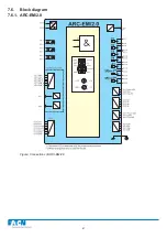
Summary of Contents for ARCON 2.0 Series
Page 51: ...51 7 6 Block diagram 7 6 1 ARC EM 2 0 Figure Connections of ARC EM 2 0...
Page 54: ...54 7 6 4 ARC EL3 2 0 7 6 5 ARC EC1 2 0...
Page 64: ...64 9 Construction 9 1 Dimensional drawings 9 1 1 ARC EM 2 0 panel and semi flush mounting...
Page 65: ...65 9 1 2 ARC EP10 2 2 0 din rail mounting...
Page 66: ...9 1 3 ARC EP10 2 0 din rail mounting 66...
Page 67: ...67 9 1 4 ARC EL3 2 0 din rail mounting...
Page 68: ...68 9 1 5 ARC EC1 2 0 din rail mounting...
Page 69: ...69 9 1 6 Fiber sensor mounting r min 50 mm...
Page 70: ...70 9 1 7 Point sensor mounting...
Page 82: ...82 10 Application examples 10 1 Applications 10 1 1 With a main busbar system...
Page 83: ...83 10 1 2 With two main busbar systems...
Page 84: ...84 10 1 3 With two main busbar systems and additional zone selection 4 zones...
Page 85: ...85...