30 Operation
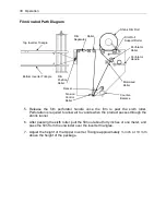
Film Unwind Path Diagram
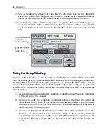
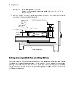
5. Release the film perforator handle once the film is past the sixth roller.
Perforation is required to allow air to vacate when the product passes through the
shrink tunnel.
6. After passing the sixth roller, pull the film out about forty inches or one meter, and
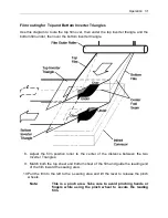
pass the film from the unwinder over the inverter triangles.
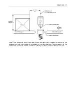
7. Adjust the height of the Upper Inverter Triangle approximately ½ inch or 13 mm
above the height of the package.
Shrink Film Roll
Roller
Film Roll
Support Roller
Perforator
Roller
Perforator
Handle
Motorized
Roller
Film
Separator
Tension
Control
Roller
Film
Position
Roller
Top Inverter Triangle
Bottom Inverter Triangle
Dancer
Counter-
Balance
Summary of Contents for Value VSA2530TK-V1
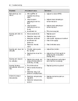
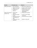
Page 1: ...VSA Value Series Auto L Sealers User Guide VSA2530TK V1 ...
Page 2: ......
Page 4: ......
Page 73: ...Appendix A Electrical Schematic 73 VSA2530 TKV1 Sheet 2 of 5 ...
Page 74: ...74 Appendix A Electrical Schematic VSA2530 TKV1 Sheet 3 of 5 ...
Page 75: ...Appendix A Electrical Schematic 75 VSA2530 TKV1 Sheet 4 of 5 ...
Page 76: ...76 Appendix A Electrical Schematic VSA2530 TKV1 Sheet 5 of 5 ...
Page 78: ...78 Appendix A Electrical Schematic VSA2530 TKV2 Sheet 2 of 6 ...
Page 79: ...Appendix A Electrical Schematic 79 VSA2530 TKV2 Sheet 3 of 6 ...
Page 80: ...80 Appendix A Electrical Schematic VSA2530 TKV2 Sheet 4 of 6 ...
Page 81: ...Appendix A Electrical Schematic 81 VSA2530 TKV2 Sheet 5 of 6 ...
Page 82: ...82 Appendix A Electrical Schematic VSA2530 TKV2 Sheet 6 of 6 ...
Page 83: ...Appendix B Air Diagram Pneumatic Schematic 83 Appendix B Air Diagram Pneumatic Schematic ...
Page 88: ......

