26 Operation
Set Temperatures and Machine Distance Settings
— Heat Elements, Transverse
Direction and Machine Direction, Infeed Conveyor Width, Film Inverter Triangle Height,
and Seal Line Height.
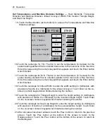
15. Touch the Next button (at the bottom) to access the Temperatures and Machine
Distance settings.
16. Touch the rectangle for T.D. Thermo to set the temperature (in Celsius) for the
sealer heating element that is oriented transverse to the main axis of the machine.
Enter the value using the numeric keypad that appears and touch the Enter button
when finished.
17. Touch the rectangle for M.D. Thermo to set the temperature (in Celsius) for the
sealer heating element that is oriented parallel to the main axis of the machine.
Enter the value using the numeric keypad that appears and touch the Enter button
when finished.
18. Touch the rectangle for Infeed Width to enter the width setting (in millimeters, with
precision of tenths of a millimeter) for the infeed conveyor. Touch Enter on the on-
screen numeric keypad when finished entering the number.
19. Touch the rectangle for Triangle Height to enter the height setting (in millimeters,
with precision of tenths of a millimeter) for the inverter triangle height. Touch Enter
on the on-screen numeric keypad when finished entering the number.
20. Touch the rectangle for Seal Line Height to enter the height setting (in millimeters
with precision of tenths of a millimeter) for the seal centerline height. Touch Enter
on the on-screen numeric keypad when finished entering the number.
21. After all values have been entered, touch the Prev. button to return to the previous
screen. Touch the Prev. button at the bottom of the screen to return to the
Recipes screen. Touch the Prev. button at the bottom of the screen to return to
the Setting tab.
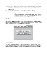
OTHER
SETTING
T.D. Thermo:
M.D. Thermo:
0
0
Infeed Width:
0.0
°C
mm
Triangle Height:
0.0
mm
Seal Line Height:
0.0
mm
WORKING
°C
PREV.
SAVE
Set
Set
Set
Set
Set
Summary of Contents for Value VSA2530TK-V1
Page 1: ...VSA Value Series Auto L Sealers User Guide VSA2530TK V1 ...
Page 2: ......
Page 4: ......
Page 73: ...Appendix A Electrical Schematic 73 VSA2530 TKV1 Sheet 2 of 5 ...
Page 74: ...74 Appendix A Electrical Schematic VSA2530 TKV1 Sheet 3 of 5 ...
Page 75: ...Appendix A Electrical Schematic 75 VSA2530 TKV1 Sheet 4 of 5 ...
Page 76: ...76 Appendix A Electrical Schematic VSA2530 TKV1 Sheet 5 of 5 ...
Page 78: ...78 Appendix A Electrical Schematic VSA2530 TKV2 Sheet 2 of 6 ...
Page 79: ...Appendix A Electrical Schematic 79 VSA2530 TKV2 Sheet 3 of 6 ...
Page 80: ...80 Appendix A Electrical Schematic VSA2530 TKV2 Sheet 4 of 6 ...
Page 81: ...Appendix A Electrical Schematic 81 VSA2530 TKV2 Sheet 5 of 6 ...
Page 82: ...82 Appendix A Electrical Schematic VSA2530 TKV2 Sheet 6 of 6 ...
Page 83: ...Appendix B Air Diagram Pneumatic Schematic 83 Appendix B Air Diagram Pneumatic Schematic ...
Page 88: ......

