Adjustments 39
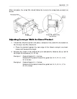
Adjusting Conveyor Width for Size of Product
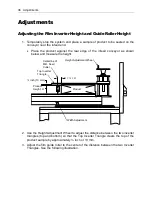
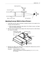
1. Temporarily stop the system and place a sample of product to be sealed on the
conveyor near the infeed end.
Place the product against the rear edge of the infeed conveyor as shown
below and measure the height.
2. Place the product against the rear edge of the infeed conveyor as shown below
and measure the height.
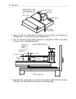
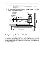
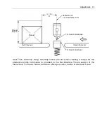
3. Measure the height of the product (H) and calculate the distance (D) as half of
the height of the product (½ × H = D).
Example 1: Product Height, H = 4 inches.
Distance from product to seal line guide bar, D = ½ H = ½ × 4 in.
D = 2 inches.
H
D
Distance (D) equals
one half Height (H),
or,
D = ½ × H.
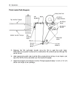
Product
Conveyor
Conveyor edge
Seal Line
Guide Bar
Top Inverter Triangle
Bottom Inverter Triangle
Height Adjustment
Film Guide Roller
1/2
1/2
Adjust
Height
Summary of Contents for Value VSA2530TK-V1
Page 1: ...VSA Value Series Auto L Sealers User Guide VSA2530TK V1 ...
Page 2: ......
Page 4: ......
Page 73: ...Appendix A Electrical Schematic 73 VSA2530 TKV1 Sheet 2 of 5 ...
Page 74: ...74 Appendix A Electrical Schematic VSA2530 TKV1 Sheet 3 of 5 ...
Page 75: ...Appendix A Electrical Schematic 75 VSA2530 TKV1 Sheet 4 of 5 ...
Page 76: ...76 Appendix A Electrical Schematic VSA2530 TKV1 Sheet 5 of 5 ...
Page 78: ...78 Appendix A Electrical Schematic VSA2530 TKV2 Sheet 2 of 6 ...
Page 79: ...Appendix A Electrical Schematic 79 VSA2530 TKV2 Sheet 3 of 6 ...
Page 80: ...80 Appendix A Electrical Schematic VSA2530 TKV2 Sheet 4 of 6 ...
Page 81: ...Appendix A Electrical Schematic 81 VSA2530 TKV2 Sheet 5 of 6 ...
Page 82: ...82 Appendix A Electrical Schematic VSA2530 TKV2 Sheet 6 of 6 ...
Page 83: ...Appendix B Air Diagram Pneumatic Schematic 83 Appendix B Air Diagram Pneumatic Schematic ...
Page 88: ......


