16 Operation
Operation
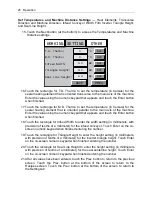
The main power switch is located on the door to the electrical panel,
which is under the product intake conveyor and film inverter.
Control Panel
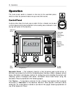
Controls other than the main power switch for the L-Sealer are located
on the hinged control panel attached to the sealing area enclosure, near
the top and center of the machine.
Operator’s Panel
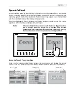
— The operator’s panel is a fully functional color touch screen. A
technical name used for this is the Human Machine Interface (HMI) It displays current
status information and displays buttons for configuring and controlling the system and
obtaining system messages and status information. More detail about using the
Operator’s Panel is explained in the following pages.
T.D. Thermo
— Temperature controller for the L-Sealer heat element that is aligned
cross-wise or
transverse
to the Machine Direction. More specific information about
setting the T.D. temperature controller is provided in the pages following explanation of
use of the Operator’s Panel.
F1
F2
F3
F4
F5
F6
F7
F8
T
O
U
C
H
SIMATIC PANEL
T.D.THERMO
M.D.THERMO
START
GREEN
STOP
RED
E-STOP
RED
PF
PV
SV
PF
PV
SV
Start
Button
Transverse
Direction
Temperature
Control
E-Stop
Button
Operator’s
Panel
Stop Button
Machine
Direction
Temperature
Control
MAIN POWER
ON
Summary of Contents for Value VSA2530TK-V1
Page 1: ...VSA Value Series Auto L Sealers User Guide VSA2530TK V1 ...
Page 2: ......
Page 4: ......
Page 73: ...Appendix A Electrical Schematic 73 VSA2530 TKV1 Sheet 2 of 5 ...
Page 74: ...74 Appendix A Electrical Schematic VSA2530 TKV1 Sheet 3 of 5 ...
Page 75: ...Appendix A Electrical Schematic 75 VSA2530 TKV1 Sheet 4 of 5 ...
Page 76: ...76 Appendix A Electrical Schematic VSA2530 TKV1 Sheet 5 of 5 ...
Page 78: ...78 Appendix A Electrical Schematic VSA2530 TKV2 Sheet 2 of 6 ...
Page 79: ...Appendix A Electrical Schematic 79 VSA2530 TKV2 Sheet 3 of 6 ...
Page 80: ...80 Appendix A Electrical Schematic VSA2530 TKV2 Sheet 4 of 6 ...
Page 81: ...Appendix A Electrical Schematic 81 VSA2530 TKV2 Sheet 5 of 6 ...
Page 82: ...82 Appendix A Electrical Schematic VSA2530 TKV2 Sheet 6 of 6 ...
Page 83: ...Appendix B Air Diagram Pneumatic Schematic 83 Appendix B Air Diagram Pneumatic Schematic ...
Page 88: ......


