20 Operation
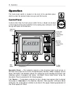
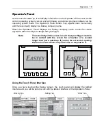
The touch panel interface is organized into three tabbed pages labeled: Other, Working,
and Settings. To view or enter information in any of the tabs, touch the tab label area
with your finger.
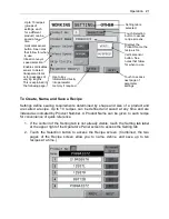
Working Tab
The Working tab is normally active during normal operation. (If not, you can view it by
touching the tab label, Working, on the touch screen.)
The Working tab shows the name of the product currently being run, and a running
counter of the number of units that have been sealed using the current product settings
or recipe. Buttons on the screen allow you immediate actions, such as to reset the
counter, and override certain functions. For example, to manually feed the product and
to seal it manually.
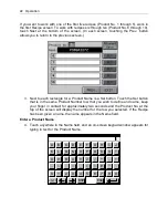
Setting Tab
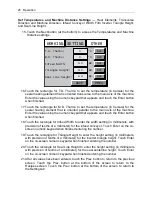
Touch the screen in the Setting tab to view and work with settings. The Setting tab
allows you to view or set up parameters for products for semi-automatic operation.
Tab areas at top for
Other, Working, and
Setting areas of the
control Interface.
A named and
saved group of
settings, or
“recipe,” defined
and selected for
the specific current
product being run.
Reset counter
button
—
Resets counter
to zero.
Counter keeps
track of the number
of items of the
product for which
seals have been
made.
Temperature
controller On / Off
buttons for heat
elements in each
direction
(transverse and
machine direction).
Move seal
center line up.
Move seal
center line
down.
Working tab is selected; tab contents are
visible; we are currently working in this tab
Manual feed
button.
Manual seal
activation button.
Summary of Contents for Value VSA2530TK-V1
Page 1: ...VSA Value Series Auto L Sealers User Guide VSA2530TK V1 ...
Page 2: ......
Page 4: ......
Page 73: ...Appendix A Electrical Schematic 73 VSA2530 TKV1 Sheet 2 of 5 ...
Page 74: ...74 Appendix A Electrical Schematic VSA2530 TKV1 Sheet 3 of 5 ...
Page 75: ...Appendix A Electrical Schematic 75 VSA2530 TKV1 Sheet 4 of 5 ...
Page 76: ...76 Appendix A Electrical Schematic VSA2530 TKV1 Sheet 5 of 5 ...
Page 78: ...78 Appendix A Electrical Schematic VSA2530 TKV2 Sheet 2 of 6 ...
Page 79: ...Appendix A Electrical Schematic 79 VSA2530 TKV2 Sheet 3 of 6 ...
Page 80: ...80 Appendix A Electrical Schematic VSA2530 TKV2 Sheet 4 of 6 ...
Page 81: ...Appendix A Electrical Schematic 81 VSA2530 TKV2 Sheet 5 of 6 ...
Page 82: ...82 Appendix A Electrical Schematic VSA2530 TKV2 Sheet 6 of 6 ...
Page 83: ...Appendix B Air Diagram Pneumatic Schematic 83 Appendix B Air Diagram Pneumatic Schematic ...
Page 88: ......


